CYLINDER BLOCK REASSEMBLY
-
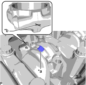
INSTALL STUD BOLT
Note
If a stud bolt is deformed or its threads are damaged, replace it.
-
Using an E6 "TORX" socket wrench, install the stud bolt labeled A to the cylinder block sub-assembly.
- Torque:
- for stud bolt A
- 6.0 N*m { 61 kgf*cm, 53 in.*lbf }
-
Using an E8 "TORX" socket wrench, install the stud bolts labeled B, D and E to the cylinder block sub-assembly.
- Torque:
- for stud bolt B, D and E
- 10 N*m { 102 kgf*cm, 7 ft.*lbf }
-
Using an E10 "TORX" socket wrench, install the stud bolt labeled C to the cylinder block sub-assembly.
- Torque:
- for stud bolt C
- 19 N*m { 194 kgf*cm, 14 ft.*lbf }
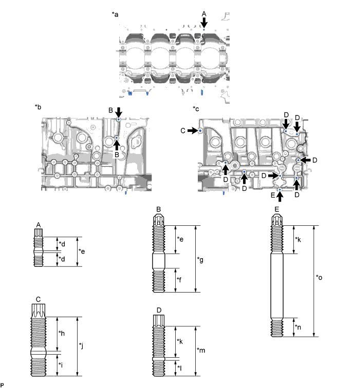
Text in Illustration *a Engine Lower Side *b Engine LH Side *c Engine RH Side *d 9.0 mm (0.354 in.) *e 19 mm (0.748 in.) *f 16 mm (0.630 in.) *g 44 mm (1.73 in.) *h 23 mm (0.906 in.) *i 15 mm (0.591 in.) *j 40 mm (1.57 in.) *k 20 mm (0.787 in.) *l 10 mm (0.394 in.) *m 32 mm (1.26 in.) *n 13 mm (0.511 in.) *o 73 mm (2.87 in.) - -
-
-
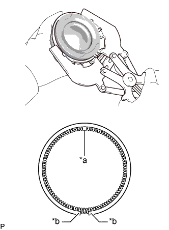
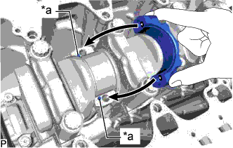
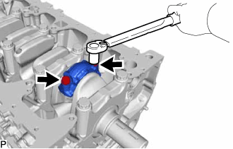
INSTALL CYLINDER BLOCK WATER DRAIN COCK SUB-ASSEMBLY
-
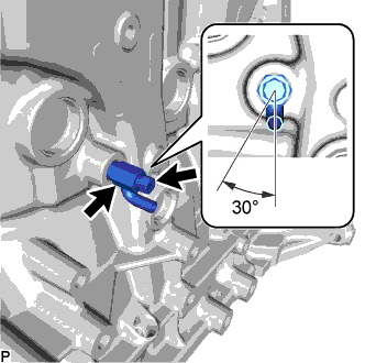
Install a new cylinder block water drain cock sub-assembly to the cylinder block sub-assembly.
- Torque:
- 25 N*m { 255 kgf*cm, 18 ft.*lbf }
Tech Tips
Install the cylinder block water drain cock sub-assembly so that the installation angle is within the range indicated by the illustration.
-
Install the cylinder block water drain cock plug to the cylinder block water drain cock sub-assembly.
- Torque:
- 13 N*m { 130 kgf*cm, 9 ft.*lbf }
-
-
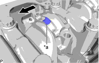
INSTALL NO. 1 OIL NOZZLE SUB-ASSEMBLY
-
Using a 5 mm hexagon wrench, install the 4 No. 1 oil nozzle sub-assemblies to the cylinder block sub-assembly with the 4 bolts.
- Torque:
- 10 N*m { 102 kgf*cm, 7 ft.*lbf }
-
-
INSTALL PISTON WITH PIN SUB-ASSEMBLY
-

Text in Illustration *1 Piston Pin Hole Snap Ring *a Service Hole Cutout Portion Using a small screwdriver, install a new piston pin hole snap ring on one side of the piston pin hole.
Tech Tips
-
Be sure that the end gap of the piston pin hole snap ring is not aligned with the service hole cutout portion of the piston.
-
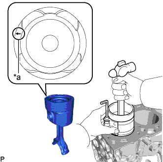
If the new piston pin is difficult to insert, heat the piston to approximately 80°C (176°F).
CAUTION:
Be sure to wear protective gloves.
-
-
Coat the piston pin with engine oil.
-
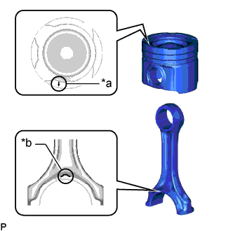
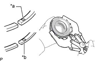
Text in Illustration *a Front Mark (Arrow) *b Front Mark (Protrusion) Align the front marks of the piston and connecting rod sub-assembly, install the connecting rod sub-assembly to the piston and push in the piston pin with your thumb.
-
Check the fitting condition between the piston and piston pin by trying to move the piston back and forth on the piston pin.
-
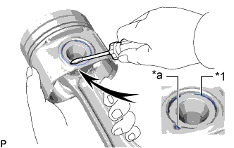
Text in Illustration *1 Piston Pin Hole Snap Ring *a Service Hole Cutout Portion Using a small screwdriver, install a new piston pin hole snap ring on one side of the piston pin hole.
Tech Tips
Be sure that the end gap of the piston pin hole snap ring is not aligned with the service hole cutout portion of the piston.
-
-
INSTALL PISTON RING SET
-
Install the oil ring expander to the piston by hand.
-
Text in Illustration *a Coil Joint *b Oil Ring Rail End Gap Using a piston ring expander, install the oil ring rail to the piston.
Tech Tips
Make sure the end gap of the oil ring rail and the coil joint are on opposite sides.
-
Text in Illustration *a No. 1 Compression Ring Code Mark *b No. 2 Compression Ring Code Mark Using a piston ring expander, install the No. 1 compression ring and No. 2 compression ring to the piston so that the code marks are positioned as shown in the illustration.
Code Mark Item Code Mark No. 1 Compression Ring G1 No. 2 Compression Ring N2 Tech Tips
Install the No. 1 compression ring and No. 2 compression ring with the code mark facing upward.
-
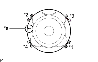
Text in Illustration *1 No. 1 Compression Ring *2 No. 2 Compression Ring *3 Oil Ring Expander *4 Oil Ring Rail *a Front Mark (Arrow) Position the piston rings so that the ring ends are as shown in the illustration.
Note
Do not align the ring ends.
-
-
INSTALL CRANKSHAFT BEARING
Tech Tips
No. 1 crankshaft bearings have an oil groove and oil hole. No. 2 crankshaft bearings do not.
-
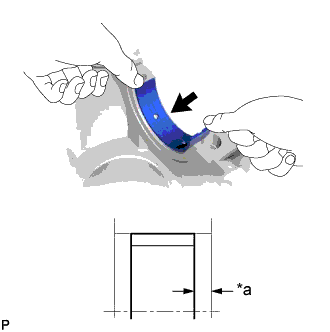
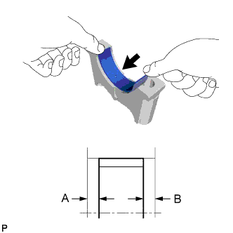
Text in Illustration *a Width Install the No. 1 crankshaft bearing to the cylinder block sub-assembly as shown in the illustration.
Standard width 4.25 mm (0.167 in.) Note
-
Clean the contact surface of the No. 1 crankshaft bearing and cylinder block sub-assembly.
-
Apply oil to the inner surface of each No. 1 crankshaft bearing (the surface which contacts the crankshaft), but not to the outer surface (the surface which contacts the cylinder block sub-assembly).
-
-
Install the No. 2 crankshaft bearing to the crankshaft bearing cap.
Note
-
Clean the contact surface of the No. 2 crankshaft bearing and crankshaft bearing cap.
-
Apply oil to the inner surface of each No. 2 crankshaft bearing (the surface which contacts the crankshaft), but not to the outer surface (the surface which contacts the crankshaft bearing cap).
-
-
Using a vernier caliper, measure the distance between the crankshaft bearing cap edge and crankshaft bearing edge.
Dimension A - B or B - A 0 to 0.7 mm (0 to 0.0276 in.)
-
-
INSTALL CRANKSHAFT
-
Apply engine oil to the crankshaft bearing, and then install the crankshaft to the cylinder block sub-assembly.
-
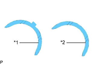
Text in Illustration *1 Lower Crankshaft Thrust Washer *2 Upper Crankshaft Thrust Washer Apply engine oil to the 2 upper crankshaft thrust washers and 2 lower crankshaft thrust washers.
Tech Tips
Check the crankshaft thrust washers, as there are different types as shown in the illustration.
-
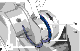
Text in Illustration *a Groove Push the crankshaft in one direction and install one upper crankshaft thrust washer to the No. 5 cylinder block sub-assembly journal position with the oil groove facing outward.
-
Push the crankshaft in the opposite direction and install the other upper crankshaft thrust washer to the No. 5 cylinder block sub-assembly journal position with the oil groove facing outward.
-
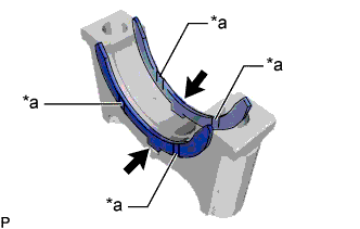
Text in Illustration *a Groove Install the 2 lower crankshaft thrust washers to the crankshaft bearing cap (No. 5 crankshaft journal) with the grooves facing outward.
-
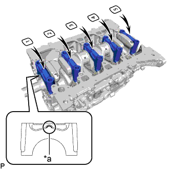
Text in Illustration *a Front Mark (Protrusion) Install the 5 crankshaft bearing caps to the cylinder block sub-assembly, making sure that the front marks (protrusions) and crankshaft bearing cap numbers of the crankshaft bearing caps are as shown in the illustration.
-
Apply a light coat of engine oil to the threads and under the heads of the crankshaft bearing cap set bolts.
-
Install the crankshaft bearing cap set bolts.
Tech Tips
-
The crankshaft bearing cap set bolts are tightened in 2 progressive steps.
-
If a crankshaft bearing cap set bolt is broken or deformed, replace it.
-
-
Step 1:
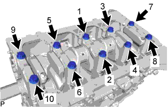
Using several steps, install and uniformly tighten the 10 crankshaft bearing cap set bolts in the sequence shown in the illustration.
- Torque:
- 95 N*m { 969 kgf*cm, 70 ft.*lbf }
Tech Tips
If any of the crankshaft bearing cap set bolts does not meet the torque specification, replace the crankshaft bearing cap set bolt.
-
Step 2:
-
Mark the front of the crankshaft bearing cap set bolts with paint.
-
Tighten the crankshaft bearing cap set bolts by 90°.
-
Check that the painted marks are now at a 90° angle to the front.
-
-
Check that the crankshaft turns smoothly.
-
-
INSPECT CRANKSHAFT THRUST CLEARANCE
-
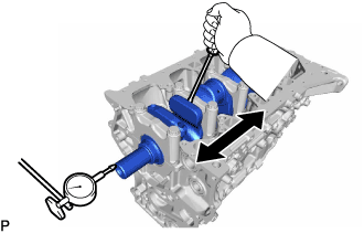
Using a dial indicator, measure the crankshaft thrust clearance while prying the crankshaft back and forth with a screwdriver.
Standard thrust clearance 0.04 to 0.24 mm (0.00157 to 0.00945 in.) Maximum thrust clearance 0.24 mm (0.00945 in.) If the thrust clearance is more than the maximum, replace the upper crankshaft thrust washers and lower crankshaft thrust washers. If necessary, replace the crankshaft.
Standard crankshaft thrust washer thickness 2.2 to 2.8 mm (0.0866 to 0.110 in.)
-
-
INSTALL CONNECTING ROD BEARING
Tech Tips
Check that the No. 1 and No. 2 connecting rod bearing colors are correct, as the colors differ.
Bearing Color: Item Connecting Rod Bearing Color No. 1 Connecting Rod Bearing Brown No. 2 Connecting Rod Bearing Silver
-
Clean the backside of the connecting rod bearing and the connecting rod bearing surface of the connecting rod sub-assembly and connecting rod cap.
-
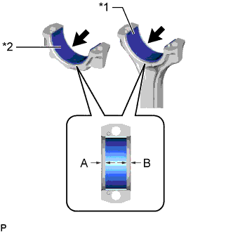
Text in Illustration *1 No. 1 Connecting Rod Bearing *2 No. 2 Connecting Rod Bearing Install the No. 1 connecting rod bearings to the connecting rod sub-assembly.
-
Install the No. 2 connecting rod bearings to the connecting rod cap.
-
Using a vernier caliper, measure the distance between the connecting rod cap edge and connecting rod bearing edge.
Dimension A - B or B - A 0 to 0.7 mm (0 to 0.0276 in.)
-
-
INSTALL PISTON AND CONNECTING ROD SUB-ASSEMBLY
-
Apply engine oil to the cylinder walls, pistons and surfaces of the connecting rod bearings.
-
Text in Illustration *1 No. 1 Compression Ring *2 No. 2 Compression Ring *3 Oil Ring Expander *4 Oil Ring Rail *a Front Mark (Arrow) Position the piston rings so that the piston ring ends are as shown in the illustration.
Note
Do not align the piston ring ends.
-
Text in Illustration *a Front Mark (Arrow) Using a piston ring compressor and hammer handle, press a piston with connecting rod sub-assembly into each cylinder with the front mark (arrow) of the piston facing forward.
-
Place the connecting rod cap on the connecting rod sub-assembly.
-
Text in Illustration *a Pin Align the pin holes of the connecting rod cap with the pins of the connecting rod sub-assembly, and then install the connecting rod cap.
-
Text in Illustration *a Front Mark (Protrusion) 
Front Check that the front mark (protrusion) of the connecting rod cap is facing forward.
-
Text in Illustration *a Front Mark (Protrusion) *b Matchmark Check that the matchmarks of the connecting rod sub-assembly and connecting rod cap are aligned.
-
-
Apply a light coat of engine oil to the threads and under the heads of the connecting rod bolts.
-
Install the connecting rod bolts.
Tech Tips
The connecting rod bolts are tightened in 2 progressive steps.
-
Step 1:
Install and alternately tighten the connecting rod bolts of each connecting rod cap in several steps.
- Torque:
- 40 N*m { 408 kgf*cm, 30 ft.*lbf }
-
Mark the front side of each connecting rod bolt with paint.
-
Step 2:
Tighten the connecting rod bolts 90°.
-
Check that the paint marks are now at a 90° angle to the front.
-
-
Check that the crankshaft turns smoothly.
-
-
INSPECT CONNECTING ROD SUB-ASSEMBLY THRUST CLEARANCE
-

Using a dial indicator, measure the thrust clearance while moving the connecting rod sub-assembly back and forth.
Standard thrust clearance 0.10 to 0.45 mm (0.00394 to 0.0177 in.) Maximum thrust clearance 0.45 mm (0.0177 in.) If the thrust clearance is more than the maximum, replace the connecting rod sub-assembly. If necessary, replace the crankshaft.
-