CYLINDER BLOCK INSPECTION
-
INSPECT NO. 1 OIL NOZZLE SUB-ASSEMBLY
-
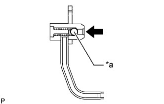
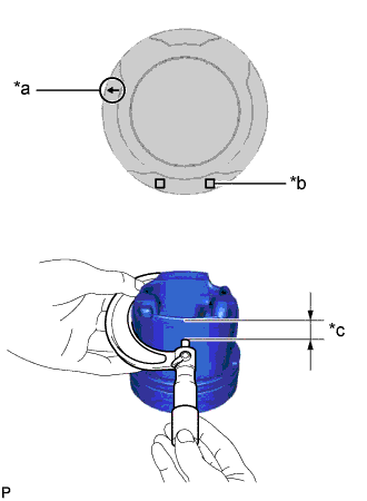
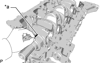
Text in Illustration *a Check Valve 
Push Push the check valve of the No. 1 oil nozzle sub-assembly to check if it is stuck.
If the check valve is stuck, replace the No. 1 oil nozzle sub-assembly.
-
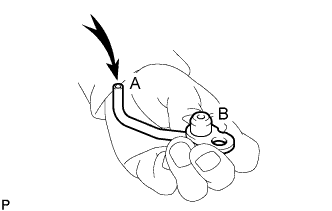
Blow air into A. Check that air does not leak from B.
Text in Illustration Air If air leaks, clean or replace the No. 1 oil nozzle sub-assembly.
-
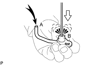
Push the check valve while blowing air into A. Check that air passes through B.
Text in Illustration Air 
Push If air does not pass through B, clean or replace the No. 1 oil nozzle sub-assembly.
-
-
CLEAN CYLINDER BLOCK SUB-ASSEMBLY
-
Using a gasket scraper, remove all the gasket material from the top surface of the cylinder block sub-assembly.
-
Using a soft brush and solvent, thoroughly clean the cylinder block sub-assembly.
-
-
INSPECT CYLINDER BLOCK SUB-ASSEMBLY FOR WARPAGE
-
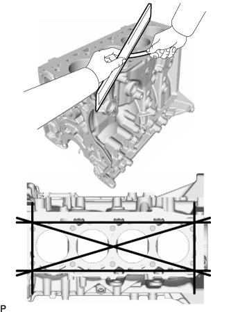
Using a precision straightedge and feeler gauge, measure the warpage of the surface where the cylinder head gasket contacts the cylinder head sub-assembly.
Maximum warpage 0.05 mm (0.00197 in.) If the warpage is more than the maximum, replace the cylinder block sub-assembly.
-
Visually check the cylinders for vertical scratches.
If deep scratches are present, replace the cylinder block sub-assembly.
-
-
INSPECT CYLINDER BORE
-
Inspect the cylinder bore diameter.
Tech Tips
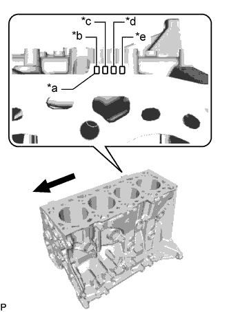
There are 2 standard cylinder bore diameter sizes, marked 1 and 2 accordingly. The mark is stamped on the cylinder block sub-assembly.
-
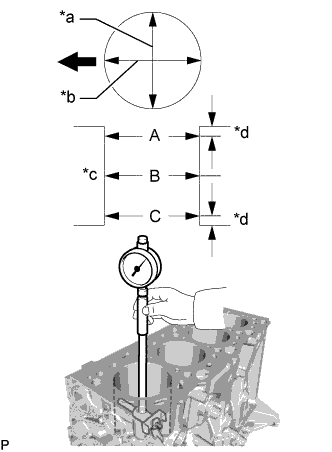
Text in Illustration *a Mark 1 or 2 *b No. 1 *c No. 2 *d No. 3 *e No. 4 Engine Front Side Using a cylinder gauge, measure the cylinder bore diameter at positions A, B and C in the thrust and axial directions.
Reference Value (New parts) Item Specified Condition Mark 1 92.005 to 92.015 mm (3.6222 to 3.6226 in.) Mark 2 92.015 to 92.025 mm (3.6226 to 3.6230 in.) Maximum diameter 92.025 mm (3.6230 in.) If the diameter is more than the maximum, replace the cylinder block sub-assembly.
-
-
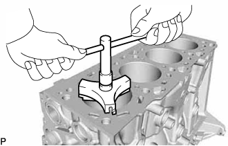
Text in Illustration *a Thrust Direction *b Axial Direction *c Center *d 10 mm (0.394 in.) Engine Front Side Inspect the cylinder ridge.
If the wear is less than 0.2 mm (0.00787 in.), using a ridge reamer, grind the top of the cylinder.
-
-
CLEAN PISTON
-
Using a gasket scraper, remove the carbon from the piston top.
-
Using a groove cleaning tool or broken piston ring, clean the piston ring grooves.
-
Using solvent and a brush, thoroughly clean the piston.
Note
Do not use a wire brush.
-
-
INSPECT PISTON DIAMETER
-
Text in Illustration *a Front Mark (Arrow) *b Piston Size Mark *c 17 mm (0.669 in.) Using a micrometer, measure the piston diameter at right angles to the piston center line where the position is 17 mm (0.669 in.) from the bottom edge of the piston.
Reference Value (New parts) Item Specified Condition Mark 1 91.931 to 91.955 mm (3.6193 to 3.6203 in.) Mark 2 91.955 to 91.965 mm (3.6203 to 3.6207 in.)
-
-
INSPECT PISTON OIL CLEARANCE
-
Measure the cylinder bore diameter in the thrust direction.
-
Subtract the piston diameter measurement from the cylinder bore diameter measurement.
Reference value (new parts) 0.040 to 0.094 mm (0.00157 to 0.00370 in.) Maximum oil clearance 0.16 mm (0.00630 in.) If the oil clearance is more than the maximum, replace all the piston with pin sub-assemblies. If necessary, replace the cylinder block sub-assembly.
-
-
INSPECT PISTON RING GROOVE CLEARANCE
-
Using a feeler gauge, measure the clearance between a new piston ring and the wall of the piston ring groove.
Standard Piston Ring Groove Clearance Item Specified Condition No. 1 Compression Ring 0.122 to 0.166 mm (0.00480 to 0.00654 in.) No. 2 Compression Ring 0.050 to 0.105 mm (0.00197 to 0.00413 in.) Oil Ring 0.030 to 0.075 mm (0.00118 to 0.00295 in.) If the result is not as specified, replace the piston with pin sub-assembly.
-
-
INSPECT PISTON RING END GAP
-
Insert the piston ring into the cylinder bore.
-
Using a piston, push the piston ring a little beyond the bottom of the ring travel, 120 mm (4.72 in.) from the top of the cylinder block sub-assembly.
-
Using a feeler gauge, measure the piston ring end gap.
Standard Piston Ring End Gap Item Specified Condition No. 1 Compression Ring 0.24 to 0.34 mm (0.00945 to 0.0134 in.) No. 2 Compression Ring 0.47 to 0.62 mm (0.0185 to 0.0244 in.) Oil Ring 0.20 to 0.40 mm (0.00787 to 0.0157 in.) Maximum Piston Ring End Gap Item Specified Condition No. 1 Compression Ring 0.34 mm (0.0134 in.) No. 2 Compression Ring 0.62 mm (0.0244 in.) Oil Ring 0.40 mm (0.0157 in.) If the end gap is more than the maximum, replace the piston ring set.
If the piston ring end gap is more than the maximum even with a new piston ring set, replace the cylinder block sub-assembly.
-
-
INSPECT PISTON PIN OIL CLEARANCE
-
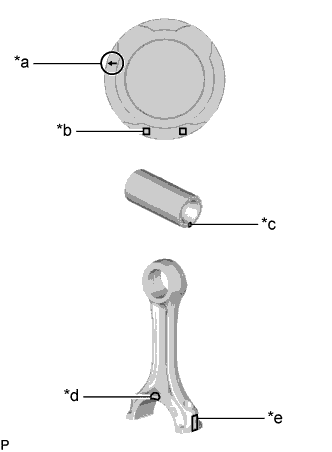
Text in Illustration *a Front Mark (Arrow) *b Piston Pin Hole Inside Diameter Mark:
Mark A, B or C
*c Piston Pin Diameter Mark:
Mark A, B or C
*d Front Mark (Protrusion) *e Connecting Rod Sub-assembly Small End Bush Inside Diameter Mark:
Mark A, B or C
Check each mark on the piston, piston pin and connecting rod sub-assembly.
-
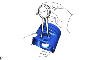
Using a caliper gauge, measure the inside diameter of the piston pin hole.
Standard Piston Pin Hole Inside Diameter Item Specified Condition Mark A 31.009 to 31.013 mm (1.2208 to 1.2210 in.) Mark B 31.013 to 31.017 mm (1.2210 to 1.2211 in.) Mark C 31.017 to 31.021 mm (1.2211 to 1.2213 in.) -
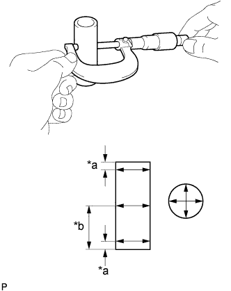
Text in Illustration *a 6.0 mm (0.236 in.) *b 33.5 mm (1.32 in.) Using a micrometer, measure the piston pin diameter.
Standard Piston Pin Diameter Item Specified Condition Mark A 31.000 to 31.004 mm (1.2205 to 1.2206 in.) Mark B 31.004 to 31.008 mm (1.2206 to 1.2208 in.) Mark C 31.008 to 31.012 mm (1.2208 to 1.2209 in.) -
Using a caliper gauge, measure the connecting rod sub-assembly small end bush inside diameter.
Standard Connecting Rod Sub-assembly Small End Bush Inside Diameter Item Specified Condition Mark A 31.019 to 31.023 mm (1.2212 to 1.2214 in.) Mark B 31.023 to 31.027 mm (1.2214 to 1.2215 in.) Mark C 31.027 to 31.031 mm (1.2215 to 1.2217 in.) -
Subtract the piston pin diameter measurement from the piston pin hole diameter measurement.
Standard piston pin oil clearance 0.005 to 0.013 mm (0.000197 to 0.000512 in.) Maximum piston pin oil clearance 0.013 mm (0.000512 in.) If the piston pin oil clearance is more than the maximum, replace the piston with pin sub-assembly.
-
Subtract the piston pin diameter measurement from the connecting rod sub-assembly small end bush inside diameter measurement.
Standard piston pin oil clearance 0.015 to 0.023 mm (0.000591 to 0.000906 in.) Maximum piston pin oil clearance 0.023 mm (0.000906 in.) If the oil clearance is more than the maximum, replace the connecting rod sub-assembly. If necessary, replace the piston with pin sub-assembly.
-
-
INSPECT CONNECTING ROD SUB-ASSEMBLY
-
Using a rod aligner and feeler gauge, check the connecting rod sub-assembly alignment.
-
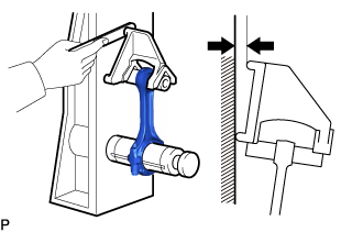
Check for bend.
Maximum bend 0.05 mm (0.00197 in.) per 100 mm (3.94 in.) If the bend is more than the maximum, replace the connecting rod sub-assembly.
-
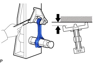
Check for twist.
Maximum twist 0.15 mm (0.00591 in.) per 100 mm (3.94 in.) If the twist is more than the maximum, replace the connecting rod sub-assembly.
-
-
-
INSPECT CONNECTING ROD BOLT
-
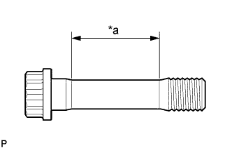
Text in Illustration *a Tension Portion Using a vernier caliper, measure the diameter of the tension portion of the connecting rod bolt.
Standard diameter 8.7 to 8.8 mm (0.343 to 0.346 in.) Minimum diameter 8.5 mm (0.335 in.) If the diameter is less than the minimum, replace the connecting rod bolt.
-
-
INSPECT CRANKSHAFT
-
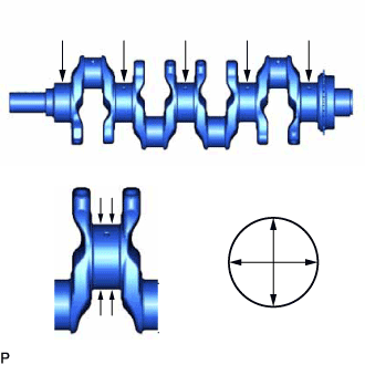
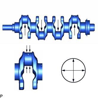
Inspect for circle runout.
-
Place the crankshaft on V-blocks.
-
Using a dial indicator, measure the circle runout at the center journal.
Maximum circle runout 0.03 mm (0.00118 in.) If the circle runout is more than the maximum, replace the crankshaft.
-
-
Inspect the main journals.
-
Using a micrometer, measure the diameter of each main journal.
Standard Main Journal Diameter Item Specified Condition Mark 1 69.994 to 70.000 mm (2.7557 to 2.7559 in.) Mark 2 69.988 to 69.994 mm (2.7554 to 2.7557 in.) Mark 3 69.982 to 69.988 mm (2.7552 to 2.7554 in.) If the diameter is not as specified, check the crankshaft oil clearance. If necessary, replace the crankshaft.
-
Check each main journal for taper and out-of round.
Maximum taper and out-of-round 0.003 mm (0.000118 in.) If the taper and out-of-round is more than the maximum, replace the crankshaft.
-
-
Inspect the crank pin.
-
Using a micrometer, measure the diameter of each crank pin.
Standard Crank Pin Diameter Item Specified Condition Mark 1 54.994 to 55.000 mm (2.1651 to 2.1654 in.) Mark 2 54.988 to 54.994 mm (2.1649 to 2.1651 in.) Mark 3 54.982 to 54.988 mm (2.1646 to 2.1649 in.) If the diameter is not as specified, check the connecting rod sub-assembly oil clearance. If necessary, replace the crankshaft.
-
Check each crank pin for taper and out-of round.
Maximum taper and out-of-round 0.003 mm (0.000118 in.) If the taper and out-of-round is more than the maximum, replace the crankshaft.
-
-
-
INSPECT CRANKSHAFT OIL CLEARANCE
-
Install the crankshaft bearings to the cylinder block sub-assembly Click here.
-
Clean each main journal and crankshaft bearings.
-
Apply engine oil to the crankshaft bearing, and then install the crankshaft to the cylinder block sub-assembly.
-
Install the crankshaft thrust washers to the cylinder block sub-assembly Click here.
-
Text in Illustration *a Plastigage Lay a strip of Plastigage across each journal.
-
Install the crankshaft bearing caps to the cylinder block sub-assembly Click here.
Note
Do not turn the crankshaft.
-
Remove the crankshaft bearing caps from the cylinder block sub-assembly Click here.
-
Measure the Plastigage at its widest point.
Standard oil clearance 0.036 to 0.042 mm (0.00142 to 0.00165 in.) Maximum oil clearance 0.048 mm (0.00189 in.) If the oil clearance is more than the maximum, replace the crankshaft bearing. If necessary, replace the crankshaft.
Tech Tips
If using a standard crankshaft bearing, replace it with one having the same number. If the number of the crankshaft bearing cannot be determined, select the correct crankshaft bearing by adding together the numbers imprinted on the cylinder block sub-assembly and crankshaft, and then selecting the crankshaft bearing with the same number as the total. There are 5 sizes of standard crankshaft bearings, marked 2, 3, 4, 5 and 6.
EXAMPLE:
Cylinder block sub-assembly (A) "3" + Crankshaft (B) "1" = Total number 4 (Use crankshaft bearing (C) "4")
Crankshaft Bearing Chart: Cylinder Block Sub-assembly (A) Crankshaft (B) Use Crankshaft Bearing (C) 1 1 2 2 3 3 4 2 1 3 2 4 3 5 3 1 4 2 5 3 6 Standard Cylinder Block Sub-assembly Main Journal Bore Diameter (A) Item Specified Condition Mark 1 75.000 to 75.006 mm (2.9528 to 2.9530 in.) Mark 2 75.006 to 75.012 mm (2.9530 to 2.9532 in.) Mark 3 75.012 to 75.018 mm (2.9532 to 2.9535 in.) Standard Crankshaft Journal Diameter (B) Item Specified Condition Mark 1 69.994 to 70.000 mm (2.7557 to 2.7559 in.) Mark 2 69.988 to 69.994 mm (2.7554 to 2.7557 in.) Mark 3 69.982 to 69.988 mm (2.7552 to 2.7554 in.) Standard Sized Crankshaft Bearing Center Wall Thickness (C) Item Specified Condition Mark 2 2.482 to 2.485 mm (0.0977 to 0.0978 in.) Mark 3 2.485 to 2.488 mm (0.0978 to 0.0980 in.) Mark 4 2.488 to 2.491 mm (0.0980 to 0.0981 in.) Mark 5 2.491 to 2.494 mm (0.0981 to 0.0982 in.) Mark 6 2.494 to 2.497 mm (0.0982 to 0.0983 in.) 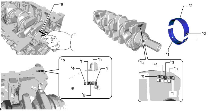
Text in Illustration *1 No. 1 Crankshaft Bearing *2 No. 2 Crankshaft Bearing *a Plastigage *b Cylinder Block Sub-assembly Main Journal Bore Diameter:
Mark 1, 2 or 3
*c Crankshaft Journal Diameter:
Mark 1, 2 or 3
*d Crankshaft Bearing:
Mark 2, 3, 4, 5 or 6
*e No. 1 *f No. 2 *g No. 3 *h No. 4 *i No. 5 - - -
Completely remove the Plastigage from the crankshaft main journal.
-
-
INSPECT CRANKSHAFT BEARING CAP SET BOLT
-
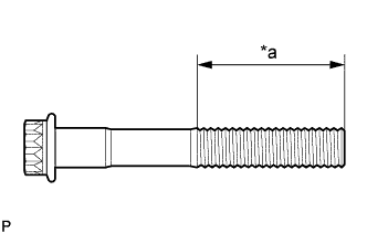
Text in Illustration *a Measuring Area Using a vernier caliper, measure the thread outside diameter of the crankshaft bearing cap set bolt.
Minimum diameter 13.7 mm (0.539 in.) If the diameter is less than the minimum, replace the crankshaft bearing cap set bolt.
-