KNOCK SENSOR INSTALLATION
-
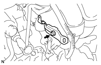
INSTALL KNOCK CONTROL SENSOR
-
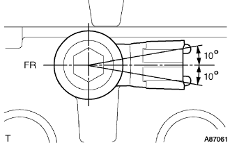
Install the bolt and knock control sensor as shown in the illustration.
- Torque:
- 20 N*m { 204 kgf*cm, 15 ft.*lbf }
-
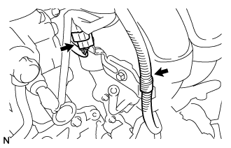
Connect the knock control sensor connector.
-
-
INSTALL INTAKE MANIFOLD
-
Install a new gasket onto the intake manifold.
-
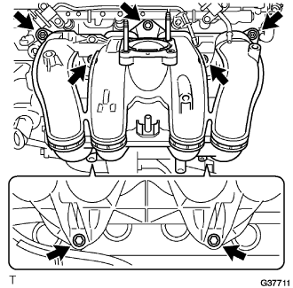
Install the 5 bolts, 2 nuts, and intake manifold.
- Torque:
- 25 N*m { 255 kgf*cm, 18 ft.*lbf }
-
Install the bolt and wire harness bracket to the intake manifold.
- Torque:
- 8.0 N*m { 82 kgf*cm, 71 in.*lbf }
-
Connect the brake booster hose and the fuel vapor feed hose with the 2 clips.
-
Connect the ventilation hose No.3 from the intake manifold.
-
Connect the 2 wire harness clamps.
-
Connect the vacuum hose and connector to the VSV.
-
-
INSTALL TRANSMISSION OIL FILLER TUBE SUB-ASSEMBLY (for Automatic Transmission)
-
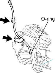
Coat a new O-ring with ATF and install the oil filler tube.
-
Install the oil filler tube with 2 bolts.
- Torque:
- 12 N*m { 125 kgf*cm, 10 ft.*lbf }
-
-
INSTALL FUEL INJECTOR ASSEMBLY
-
Apply a light coat of grease or gasoline to new O-rings and install them to the injector spacers.
Note
Make sure that the O-rings are installed between the parts correctly.
-
Install the injection spacers.
-
Apply a light coat of grease or gasoline to the place where the delivery pipe touches the O-ring.
-
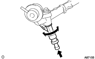
To install the fuel injector into the fuel delivery pipe, push the fuel injector while twisting it right and left.
Note
-
Be careful not to twist the O-ring.
-
After installing the fuel injector, check that it turns smoothly. If not, reinstall it with a new O-ring.
-
-
-
INSTALL FUEL DELIVERY PIPE SUB-ASSEMBLY
-
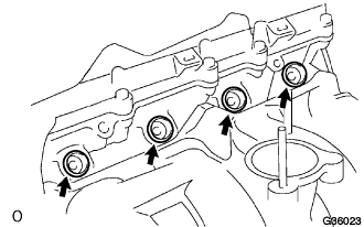
Install the 4 spacers to the cylinder head.
-
Install the delivery pipe spacers.
-
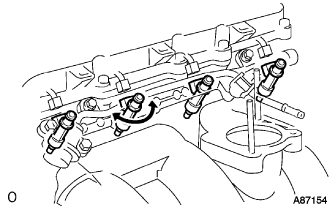
Temporarily install the 2 bolts and fuel delivery pipe together with the 4 injectors.
Note
-
Do not drop the fuel injector when installing the fuel delivery pipe.
-
Make sure that the fuel injector turns smoothly.
-
-
Fully tighten the 2 bolts.
- Torque:
- 12 N*m { 122 kgf*cm, 10 ft.*lbf }
-
Apply a light coat of grease or gasoline to the place where the delivery pipe touches the O-ring.
-
Install the 2 bolts and pressure pulsation damper assembly.
- Torque:
- 8.5 N*m { 87 kgf*cm, 75 in.*lbf }
-
Connect the 2 fuel hoses.
-
-
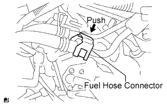
INSTALL FUEL HOSE
-
Align the connector and pipe. Push on the connector until the retainer locks with a click sound. Click here
-
Pull the connector to check that the connector is securely connected. Click here
-
Install the connector and lock it with the fuel hose connector cover. Click here
-
-
INSTALL THROTTLE BODY ASSEMBLY
-
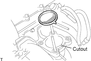
Install a new gasket onto the intake manifold.
Tech Tips
Fit the gasket to the cutout of the intake manifold.
-
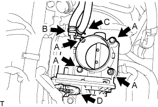
for Type A:
Install the throttle body assembly with the 2 bolts and 2 nuts. (A)
- Torque:
- 9.0 N*m { 92 kgf*cm, 80 in.*lbf }
-
for Type B:
Install the throttle body assembly with the 4 bolts. (A)
- Torque:
- 9.0 N*m { 92 kgf*cm, 80 in.*lbf }
-
Connect the water by-pass hose, and slide the clamp to secure it. (B)
-
Connect the No. 2 water by-pass hose, and slide the clamp to secure it. (C)
-
Connect the throttle motor connector. (D)
-
-
INSTALL INTAKE AIR CONNECTOR
-
Temporarily install the intake air connector to the throttle body assembly.
-
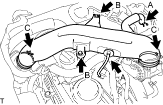
Connect the No. 2 ventilation hose and vacuum hose, and slide the clamp to secure it. (A)
-
Install the intake air connector with the 2 bolts. (B)
- Torque:
- 8.0 N*m { 82 kgf*cm, 71 in.*lbf }
-
Tighten the 2 hose clamp bolts. (C)
- Torque:
- 5.0 N*m { 51 kgf*cm, 44 in.*lbf }
-
-
INSTALL ENGINE SERVICE HOLE SUB COVER SUB-ASSEMBLY
-
Install the engine service hole cover with the 5 bolts.
- Torque:
- 13 N*m { 133 kgf*cm, 10 ft.*lbf }
-
-
INSTALL FRONT DOOR SCUFF PLATE RH
-
INSTALL FRONT SEAT ASSEMBLY RH (for Hi-back Seat Type)
-
Perform the same procedure as above on the opposite side. Click here
-
-
INSTALL FRONT SEAT ASSEMBLY RH (for Low-back Seat Type)
-
Perform the same procedure as above on the opposite side. Click here
-
-
ADD ENGINE COOLANT
-
Tighten the radiator drain cock plug by hand.
-
Tighten the cylinder block water drain cock plug.
- Torque:
- 13 N*m { 130 kgf*cm, 9 ft.*lbf }
-
Fill the radiator reservoir assembly with engine coolant to the top of the inlet.
Standard Capacity Item Specified Condition w/o Rear Heater 11.2 liters (11.8 US qts, 9.9 Imp. qts) w/ Rear Heater 13.2 liters (13.9 US qts, 11.6 Imp. qts) Note
Never use water as a substitute for engine coolant.
Tech Tips
TOYOTA vehicles are filled with TOYOTA SLLC at the factory. In order to avoid damage to the engine cooling system and other technical problems, only use TOYOTA SLLC or similar high quality ethylene glycol based non-silicate, non-amine, non-nitrite, non-borate coolant with long-life hybrid organic acid technology (coolant with long-life hybrid organic acid technology is a combination of low phosphates and organic acids).
-
Remove the 2-way that is located near the throttle body assembly.
-
When air is bled and the engine coolant drains out, install the 2-way.
-
Add coolant through the radiator reservoir assembly filler opening until the coolant reaches the B line and install the radiator reservoir cap sub-assembly. [*1]
-
Warm up the engine until the thermostat opens. While the thermostat is open, circulate the coolant for several minutes. [*2]
CAUTION:
-
Wear protective gloves.
-
Be careful as the radiator hoses are hot.
-
Keep your hands away from the radiator fans.
Note
-
Immediately after starting the engine, if the radiator reservoir assembly does not have any engine coolant, perform the following: 1) stop the engine, 2) wait until the engine coolant has cooled down, and 3) add engine coolant.
-
Do not start the engine when there is no engine coolant in the radiator reservoir assembly.
-
Make sure that the needle does not show an abnormally high temperature.
-
If there is not enough engine coolant, the engine may overheat.
Tech Tips
-
Press the No. 2 and No. 3 radiator hoses several times by hand, and then check the level of the engine coolant.
-
The thermostat open timing can be confirmed by pressing the No. 3 radiator hose by hand, and checking when the engine coolant starts to flow inside the hose.
-
-
Stop the engine, and wait until the engine coolant cools down to ambient temperature. [*3]
-
Check the engine coolant level in the radiator reservoir assembly. [*4]
Tech Tips
-
If the engine coolant level is below the LOW line, repeat step *1 through *4.
-
If the engine coolant level is above the FULL line, drain engine coolant until the engine coolant level is between the FULL and LOW lines.
-
-
-
CONNECT CABLE TO NEGATIVE BATTERY TERMINAL
-
CHECK FOR ENGINE COOLANT LEAKS
-
INSTALL ENGINE UNDER COVER NO.2 (w/ Engine Under Cover No.2)
-
Install the engine under cover No.2 together with the engine side under cover LH and engine side under cover RH (for Wide Body).
- Torque:
- 13 N*m { 133 kgf*cm, 10 ft.*lbf }
-
-
INSTALL ENGINE UNDER COVER NO.1 (w/ Engine Under Cover No.1)
- Torque:
- 13 N*m { 133 kgf*cm, 10 ft.*lbf }