VALVE CLEARANCE ADJUSTMENT
Note
-
When replacing the injectors (including shuffling the injectors between the cylinders), common rail or cylinder head, it is necessary to replace the injection pipes with new ones.
-
When replacing the fuel supply pump, common rail, cylinder block, cylinder head, cylinder head gasket or timing gear case, it is necessary to replace the fuel inlet pipe with a new one.
-
After removing the injection pipes, clean them with a brush and compressed air.
Tech Tips
The injectors do not need to be removed when inspecting the valve clearance.
-
REMOVE CYLINDER HEAD COVER SUB-ASSEMBLY
-
w/ DPF: Click here
-
w/o DPF: Click here
-
-
SET NO. 1 CYLINDER TO TDC/COMPRESSION
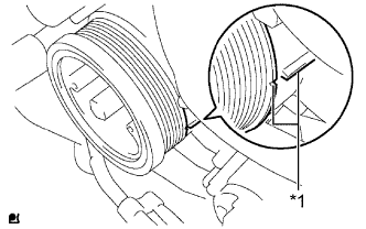
Text in Illustration *1 Matchmark
-
Align the matchmarks of the crankshaft pulley and timing gear case cover by rotating the crankshaft clockwise.
Tech Tips
Make sure that both cam lobes (intake side and exhaust side) of the No. 1 cylinder face upward.
-
-
INSPECT VALVE CLEARANCE
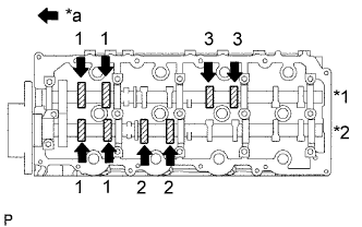
Text in Illustration *1 Exhaust *2 Intake *a Front
-
Check only the valves indicated.
-
Using a feeler gauge, measure the clearance between the valve lifter and camshaft.
Standard Valve Clearance (Cold) Item Specified Condition Intake 0.20 to 0.30 mm (0.008 to 0.012 in.) Exhaust 0.35 to 0.45 mm (0.014 to 0.018 in.) Write down any valve clearance measurements that are not within the specified range. These measurements will be used later to determine the size of the adjustment lifter to be installed.
-
-
Turn the crankshaft 360° to set the No. 4 cylinder to TDC/compression.
-
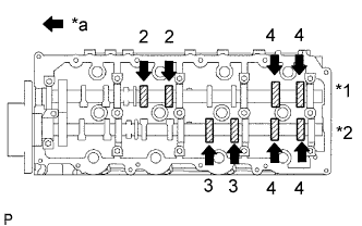
Text in Illustration *1 Exhaust *2 Intake *a Front Check only the valves indicated.
-
Using a feeler gauge, measure the clearance between the valve lifter and camshaft.
Standard Valve Clearance Item Specified Condition Intake 0.20 to 0.30 mm (0.008 to 0.012 in.) Exhaust 0.35 to 0.45 mm (0.014 to 0.018 in.) Write down any valve clearance measurements that are not within the specified range. These measurements will be used later to determine the size of the adjustment lifter to be installed.
-
-
-
ADJUST VALVE CLEARANCE
-
Remove the camshafts Click here.
-
Remove the valve lifters.
-
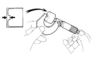
Using a micrometer, measure the thickness of the removed lifter.
-
Calculate the thickness of a new lifter so that the valve clearance is within the specified range.
A B C New lifter thickness Used lifter thickness Measured valve clearance New lifter thickness Intake: A = B + (C - 0.25 mm (0.0098 in.)) Exhaust: A = B + (C - 0.40 mm (0.00158 in.)) -
Select a new lifter with a thickness as close as possible to the calculated values.
Tech Tips
Valve lifters are available in 35 sizes in increments of 0.020 mm (0.0008 in.), from 5.060 mm (0.1992 in.) to 5.740 mm (0.2260 in.).
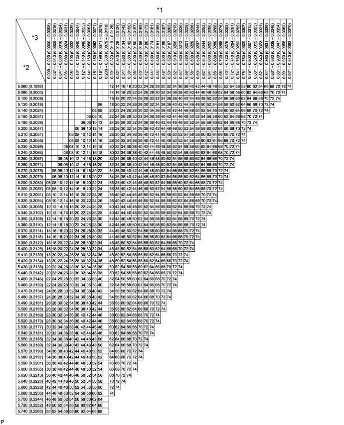
Text in Illustration *1 Valve Lifter Selection Chart (Intake) *2 Installed lifter thickness mm (in.) *3 Measured clearance mm (in.) - - Standard intake valve clearance (Cold) 0.20 to 0.30 mm (0.008 to 0.012 in.) EXAMPLE A 5.250 mm (0.2067 in.) lifter is installed, and the measured clearance is 0.400 mm (0.0158 in.). Replace the 5.250 mm (0.2067 in.) lifter with a No. 40 lifter. New Lifter Thickness Lifter No. Specified Condition Lifter No. Specified Condition Lifter No. Specified Condition 06 5.060 mm (0.1992 in.) 30 5.300 mm (0.2087 in.) 54 5.540 mm (0.2181 in.) 08 5.080 mm (0.2000 in.) 32 5.320 mm (0.2094 in.) 56 5.560 mm (0.2189 in.) 10 5.100 mm (0.2008 in.) 34 5.340 mm (0.2102 in.) 58 5.580 mm (0.2197 in.) 12 5.120 mm (0.2016 in.) 36 5.360 mm (0.2110 in.) 60 5.600 mm (0.2205 in.) 14 5.140 mm (0.2024 in.) 38 5.380 mm (0.2118 in.) 62 5.620 mm (0.2213 in.) 16 5.160 mm (0.2031 in.) 40 5.400 mm (0.2126 in.) 64 5.640 mm (0.2220 in.) 18 5.180 mm (0.2039 in.) 42 5.420 mm (0.2134 in.) 66 5.660 mm (0.2228 in.) 20 5.200 mm (0.2047 in.) 44 5.440 mm (0.2142 in.) 68 5.680 mm (0.2236 in.) 22 5.220 mm (0.2055 in.) 46 5.460 mm (0.2150 in.) 70 5.700 mm (0.2244 in.) 24 5.240 mm (0.2063 in.) 48 5.480 mm (0.2157 in.) 72 5.720 mm (0.2252 in.) 26 5.260 mm (0.2071 in.) 50 5.500 mm (0.2165 in.) 74 5.740 mm (0.2260 in.) 28 5.280 mm (0.2079 in.) 52 5.520 mm (0.2173 in.) - - 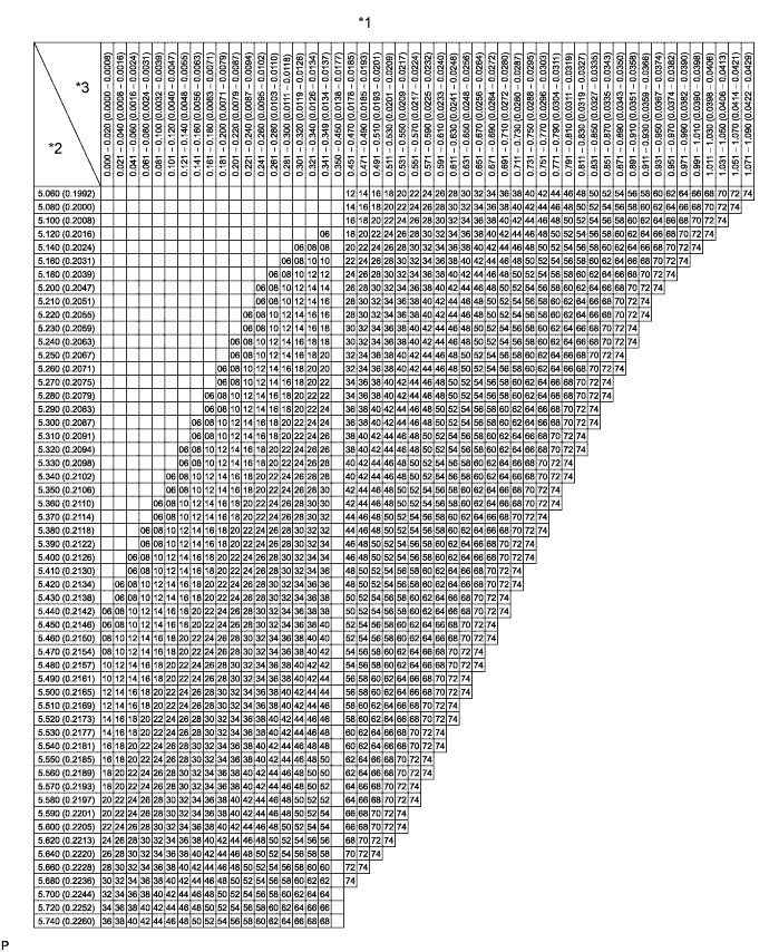
Text in Illustration *1 Valve Lifter Selection Chart (Exhaust) *2 Installed lifter thickness mm (in.) *3 Measured clearance mm (in.) - - Standard exhaust valve clearance (Cold) 0.35 to 0.45 mm (0.014 to 0.018 in.) EXAMPLE A 5.340 mm (0.2102 in.) lifter is installed, and the measured clearance is 0.480 mm (0.0189 in.). Replace the 5.340 mm (0.2102 in.) lifter with a No. 42 lifter. New Lifter Thickness Lifter No. Specified Condition Lifter No. Specified Condition Lifter No. Specified Condition 06 5.060 mm (0.1992 in.) 30 5.300 mm (0.2087 in.) 54 5.540 mm (0.2181 in.) 08 5.080 mm (0.2000 in.) 32 5.320 mm (0.2094 in.) 56 5.560 mm (0.2189 in.) 10 5.100 mm (0.2008 in.) 34 5.340 mm (0.2102 in.) 58 5.580 mm (0.2197 in.) 12 5.120 mm (0.2016 in.) 36 5.360 mm (0.2110 in.) 60 5.600 mm (0.2205 in.) 14 5.140 mm (0.2024 in.) 38 5.380 mm (0.2118 in.) 62 5.620 mm (0.2213 in.) 16 5.160 mm (0.2031 in.) 40 5.400 mm (0.2126 in.) 64 5.640 mm (0.2220 in.) 18 5.180 mm (0.2039 in.) 42 5.420 mm (0.2134 in.) 66 5.660 mm (0.2228 in.) 20 5.200 mm (0.2047 in.) 44 5.440 mm (0.2142 in.) 68 5.680 mm (0.2236 in.) 22 5.220 mm (0.2055 in.) 46 5.460 mm (0.2150 in.) 70 5.700 mm (0.2244 in.) 24 5.240 mm (0.2063 in.) 48 5.480 mm (0.2157 in.) 72 5.720 mm (0.2252 in.) 26 5.260 mm (0.2071 in.) 50 5.500 mm (0.2165 in.) 74 5.740 mm (0.2260 in.) 28 5.280 mm (0.2079 in.) 52 5.520 mm (0.2173 in.) - - -
Install the selected valve lifters.
-
Install the camshafts Click here.
-
-
INSTALL CYLINDER HEAD COVER SUB-ASSEMBLY
-
w/ DPF: Click here
-
w/o DPF: Click here
-