SFI SYSTEM (w/ Dual VVT-i), Diagnostic DTC:P1602
| DTC Code | DTC Name |
|---|---|
| P1602 | Deterioration of Battery |
DESCRIPTION
The ECM monitors the battery. When the engine is running (not cranking) and the battery voltage drops below a specified level, the ECU determines that there is battery deterioration and stores this DTC.
| DTC Code | DTC Detection Condition | Trouble Area |
|---|---|---|
| P1602 |
|
|
MONITOR STRATEGY
| Frequency of operation | Continuous |
CONFIRMATION DRIVING PATTERN
-
Connect the GTS to the DLC3.
-
Turn the ignition switch to ON and turn the GTS on.
-
Clear the DTCs (even if no DTCs are stored, perform the clear DTC operation).
-
Turn the ignition switch off and wait for at least 30 seconds.
-
Turn the ignition switch to ON and turn the GTS on.
-
Start the engine with all the accessories switched off.
-
Wait for 10 seconds or more.
-
Enter the following menus: Powertrain / Engine and ECT / Trouble Code.
-
Read Pending DTCs.
Tech Tips
-
If a pending DTC is output, the system is malfunctioning.
-
If a pending DTC is not output, perform the following procedure.
-
-
Enter the following menus: Powertrain / Engine and ECT / Utility / All Readiness.
-
Input the DTC: P1602.
-
Check the DTC judgment result.
GTS Display Description NORMAL
-
DTC judgment completed
-
System normal
ABNORMAL
-
DTC judgment completed
-
System abnormal
INCOMPLETE
-
DTC judgment not completed
-
Perform driving pattern after confirming DTC enabling conditions
N/A
-
Unable to perform DTC judgment
-
Number of DTCs which do not fulfill DTC preconditions has reached ECU memory limit
Tech Tips
-
If the judgment result shows NORMAL, the system is normal.
-
If the judgment result shows ABNORMAL, the system has a malfunction.
-
If the judgment result shows INCOMPLETE or N/A, perform the Confirmation Driving Pattern and check the DTC judgment result again.
-
WIRING DIAGRAM
Refer to DTC P0560 Click here.
INSPECTION PROCEDURE
Note
Inspect the fuses for circuits related to this system before performing the following inspection procedure.
PROCEDURE
-
CHECK FOR ANY OTHER DTCS OUTPUT
-
Connect the GTS to the DLC3.
-
Turn the ignition switch to ON.
-
Turn the GTS on.
-
Enter the following menus: Powertrain / Engine and ECT / Trouble Codes.
-
Read the DTCs.
Result Result Proceed to Only DTC P1602 is output. A Other DTCs are output in addition to DTC P1602. B
B 
GO TO DTC CHART Click here
A 
-
-
CHECK CHARGING SYSTEM
-
Check the charging system Click here.
NG
REPAIR OR REPLACE CHARGING SYSTEM
OK
-
-
CHECK HARNESS AND CONNECTOR (POWER SOURCE CIRCUIT)
-
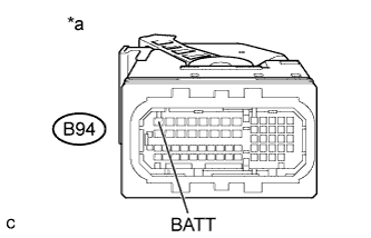
Text in Illustration *a Front view of wire harness connector
(to ECM)
Disconnect the ECM connector.
-
Measure the voltage according to the value(s) in the table below.
Standard Voltage Tester Connection Condition Specified Condition B94-1 (BATT) - Body ground Always 9.5 to 16 V
NG
REPAIR OR REPLACE HARNESS OR CONNECTOR (POWER SOURCE CIRCUIT)
OK 
CHECK FOR INTERMITTENT PROBLEMS Click here
-