SFI SYSTEM (w/o Secondary Air Injection System) Starter Signal Circuit
DESCRIPTION
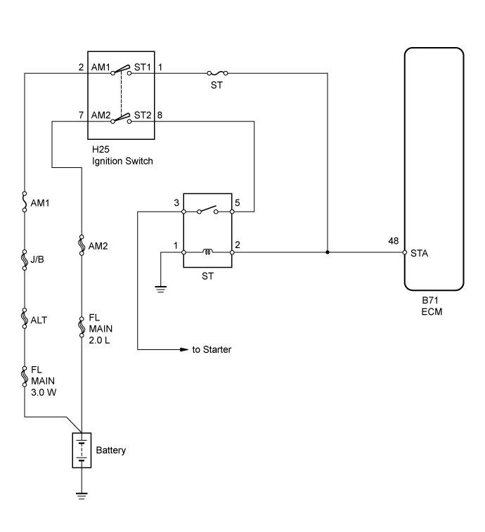
While the engine is being cranked, current flows from terminal ST1 of the ignition switch directly to terminal STA of the ECM (STA signal).
WIRING DIAGRAM
INSPECTION PROCEDURE
Note
Inspect the fuses for circuits related to this system before performing the following inspection procedure.
Tech Tips
This inspection procedure is based on the premise that the engine can crank normally. If the engine cannot crank normally, proceed to the problem symptoms table Click here.
PROCEDURE
-
READ VALUE USING INTELLIGENT TESTER (STARTER SIGNAL)
-
Connect the intelligent tester to the DLC3.
-
Turn the ignition switch to ON.
-
Turn the intelligent tester on.
-
Enter the following menus: Powertrain / Engine and ECT / Data List / Starter Signal.
-
Read the value.
OK Ignition Switch Position Starter Signal ON OFF START ON
NG 
CHECK HARNESS AND CONNECTOR (IGNITION SWITCH - ECM) Click here
OK 
PROCEED TO NEXT SUSPECTED AREA SHOWN IN PROBLEM SYMPTOMS TABLE Click here
-
-
CHECK HARNESS AND CONNECTOR (IGNITION SWITCH - ECM)
-
Disconnect the ignition switch connector.
-
Disconnect the ECM connector.
-
Remove the starter (ST) relay from the instrument panel relay block.
-
Measure the resistance according to the value(s) in the table below.
Standard Resistance Tester Connection Condition Specified Condition H25-1 (ST1) - B71-48 (STA) Always Below 1 Ω H25-1 (ST1) or B71-48 (STA) - Body ground Always 10 kΩ or higher
NG 
REPAIR OR REPLACE HARNESS OR CONNECTOR
OK 
-
-
INSPECT IGNITION SWITCH
-
Inspect the ignition switch Click here.
NG
REPLACE IGNITION SWITCH
OK
REPAIR OR REPLACE HARNESS OR CONNECTOR (BATTERY - IGNITION SWITCH)
-