CRANKSHAFT POSITION SENSOR INSTALLATION
-
INSTALL CRANKSHAFT POSITION SENSOR
-
Apply a light coat of engine oil to the O-ring of the crankshaft position sensor.
-
Install the crankshaft position sensor with the bolt.
- Torque:
- 8.5 N*m { 87 kgf*cm, 75 in.*lbf }
Note
-
When reusing the crankshaft position sensor, inspect the O-ring.
-
Make sure that the O-ring is not cracked or jammed when installing the crankshaft position sensor.
-
Connect the crankshaft position sensor connector and attach the 2 wire harness clamps.
-
-
INSTALL NO. 1 COMPRESSOR MOUNTING BRACKET
Note
Install the No. 1 compressor mounting bracket exactly as described in the procedures below to properly secure and prevent damage to the fan and generator V belt.
-
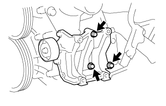
Temporarily install the No. 1 compressor mounting bracket with the 3 bolts.
Tech Tips
Temporarily install the No. 1 compressor mounting bracket with the 3 bolts so that the bracket can be moved by hand.
-
Push the No. 1 compressor mounting bracket toward the cylinder block as shown in the illustration and tighten bolt B.
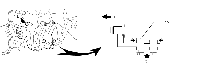
Text in Illustration *a Front *b No Clearance *c Push - - - Torque:
- Bolt B
- 45 N*m { 459 kgf*cm, 33 ft.*lbf }
Tech Tips
Make sure there is no clearance between the cylinder block and No. 1 compressor mounting bracket as shown in the illustration.
-
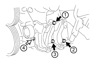
Uniformly tighten the 4 bolts in the order shown in the illustration.
Text in Illustration 
Bolt A 
Bolt C - Torque:
- Bolt A
- 45 N*m { 459 kgf*cm, 33 ft.*lbf }
- Bolt C
- 25 N*m { 255 kgf*cm, 18 ft.*lbf }
-
-
CONNECT COOLER COMPRESSOR ASSEMBLY
-
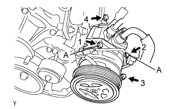
Temporarily install the bolt A to connect the compressor and magnetic clutch.
-
Connect the compressor and magnetic clutch completely by tightening the 4 bolts in the order shown in the illustration.
- Torque:
- 25 N*m { 250 kgf*cm, 18 ft.*lbf }
Note
In order to prevent misalignment, which causes belt rattle, tightening of the bolts must be performed in the order shown.
-
Connect the compressor and magnetic clutch connector.
-
-
INSTALL FAN AND GENERATOR V BELT
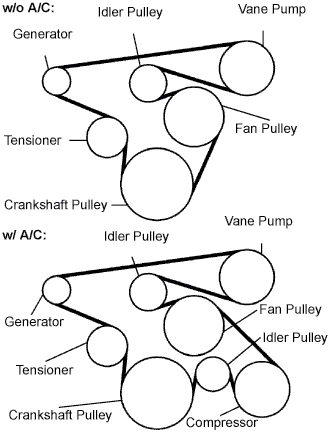
-
Install the drive belt to the pulleys except the drive belt tensioner pulley.
-
Use the hexagon-shaped part indicated by the arrow in the illustration to move the tensioner pulley downward and then install the drive belt to the tensioner pulley.
Note
-
The backside of the drive belt should face the tensioner pulley.
-
Check that the drive belt is properly set to each pulley.
-
-
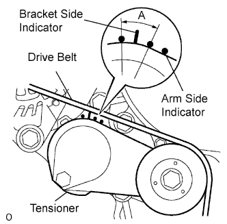
After a new belt has been installed, check that the tensioner indicator mark is within range A shown in the illustration.
-
-
INSTALL ENGINE OIL LEVEL DIPSTICK GUIDE
-
Install a new O-ring and the engine oil level dipstick guide with the bolt to the front No. 1 engine mounting bracket LH.
- Torque:
- 20 N*m { 204 kgf*cm, 15 ft.*lbf }
-
-
INSTALL ENGINE SERVICE HOLE SUB COVER SUB-ASSEMBLY
-
Install the engine service hole cover sub-assembly with the 5 bolts.
- Torque:
- 13 N*m { 133 kgf*cm, 10 ft.*lbf }
-
-
INSTALL FRONT DOOR SCUFF PLATE RH
-
INSTALL FRONT SEAT ASSEMBLY RH
-
CONNECT CABLE TO NEGATIVE BATTERY TERMINAL
Note
When disconnecting the cable, some systems need to be initialized after the cable is reconnected Click here.