OIL PUMP INSTALLATION

-
INSTALL OIL PUMP RELIEF VALVE
-
Coat the relief valve with engine oil.
-
Insert the relief valve and spring into the timing chain cover hole.
-
Install a new gasket to the plug.
-
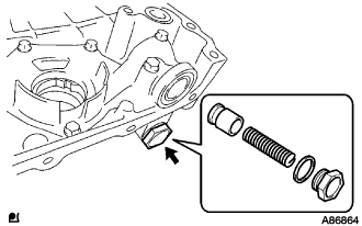
Using a 27 mm socket wrench, install the plug.
- Torque:
- 49 N*m { 500 kgf*cm, 36 ft.*lbf }
-
-
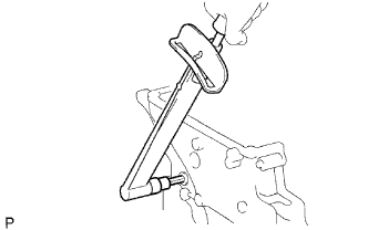
INSTALL TIMING GEAR CASE OR TIMING CHAIN CASE OIL SEAL
-
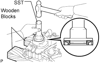
Place the timing chain cover on wooden blocks.
-
Using SST, tap in a new oil seal until its surface is flush with the timing gear case edge.
- SST
- 09223-50010
Note
-
Keep the lip free from foreign matter.
-
Do not tap the oil seal at an angle.
-
-
INSTALL WATER PUMP ASSEMBLY
-
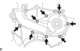
Install a new gasket and the water pump with the 8 bolts.
- Torque:
- 8.9 N*m { 91 kgf*cm, 79 in.*lbf }
-
-
INSTALL TIMING CHAIN OR BELT COVER SUB-ASSEMBLY
-
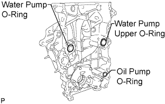
Install 3 new O-rings to the timing chain cover as shown in the illustration.
-
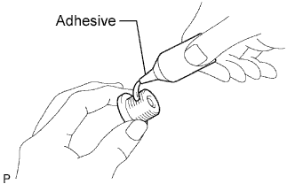
Apply adhesive to the timing chain cover plug.
Adhesive Toyota Genuine Adhesive 1324, Three Bond 1324 or equivalent -
Using a 10 mm socket hexagon wrench, install the timing chain cover plug.
- Torque:
- 17 N*m { 170 kgf*cm, 12 ft.*lbf }
-
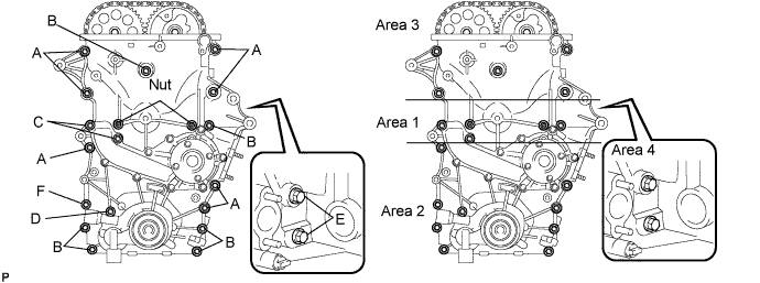
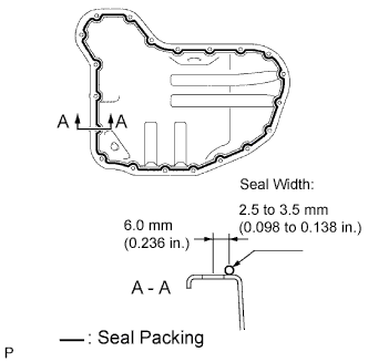
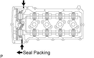
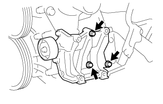
Apply seal packing in a continuous bead to the timing chain cover as shown in the following illustration.
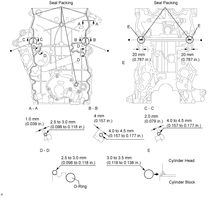
Seal packing Toyota Genuine Seal Packing Black, Three Bond 1207B or equivalent Seal width Position Specified Condition A - A 2.5 to 3.0 mm (0.098 to 0.118 in.) B - B, C - C 4.0 to 4.5 mm (0.157 to 0.177 in.) D - D 2.5 to 3.0 mm (0.098 to 0.118 in.) E 3.0 to 3.5 mm (0.118 to 0.138 in.) Note
-
Be sure to clean and degrease the contact surfaces, especially 4 areas indicated by in the illustration.
-
When the contact surfaces are wet, wipe off with an oil-free cloth before applying seal packing.
-
Install the crankcase within 3 minutes and tighten the bolts within 15 minutes after applying seal packing.
-
Do not start the engine for at least 4 hours after installing.
-
-
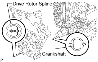
Align the oil pump's drive rotor spline and the crankshaft as shown in the illustration. Install the spline and chain cover to the crankshaft.
-
Install the timing chain cover (w/o air conditioning).
-
Loosely install the timing chain cover with the 19 bolts and 2 nuts, but do not tighten the bolts and nuts yet.
-
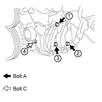
Tighten the bolts labeled B, C and D and the nuts in this order: area 1, area 3, area 2.
- Torque:
- for bolt C
- 26 N*m { 265 kgf*cm, 19 ft.*lbf }
- for bolt B, D and nut
- 21 N*m { 214 kgf*cm, 15 ft.*lbf }
Bolt Length Item Length Thread Diameter Bolt A 75 mm (2.95 in.) 10 mm (0.394 in.) Bolt B 75 mm (2.95 in.) 8 mm (0.315 in.) Bolt C 87 mm (3.43 in.) 8 mm (0.315 in.) Bolt D 95 mm (3.74 in.) 8 mm (0.315 in.) Bolt E 35 mm (1.38 in.) 8 mm (0.315 in.) Bolt F 75 mm (2.95 in.) 10 mm (0.394 in.) -
Tighten the bolts labeled A and F in this order: area 2, area 3.
- Torque:
- for bolt A
- 60 N*m { 612 kgf*cm, 44 ft.*lbf }
- for bolt F
- 46 N*m { 469 kgf*cm, 34 ft.*lbf }
-
Tighten the bolts labeled E in area 4.
- Torque:
- 21 N*m { 214 kgf*cm, 15 ft.*lbf }
-
-
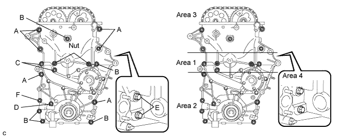
Install the timing chain cover (w/ air conditioning).
-
Loosely install the timing chain cover with the 17 bolts and 2 nuts, but do not tighten the bolts and nuts yet.
-
Tighten the bolts labeled B, C and D and the nuts in this order: area 1, area 3, area 2.
- Torque:
- for bolt C
- 26 N*m { 265 kgf*cm, 19 ft.*lbf }
- for bolt B, D and nut
- 21 N*m { 214 kgf*cm, 15 ft.*lbf }
Bolt Length Item Length Thread Diameter Bolt A 75 mm (2.95 in.) 10 mm (0.394 in.) Bolt B 75 mm (2.95 in.) 8 mm (0.315 in.) Bolt C 87 mm (3.43 in.) 8 mm (0.315 in.) Bolt D 95 mm (3.74 in.) 8 mm (0.315 in.) Bolt E 35 mm (1.38 in.) 8 mm (0.315 in.) Bolt F 75 mm (2.95 in.) 10 mm (0.394 in.) -
Tighten the bolts labeled A and F in this order: area 2, area 3.
- Torque:
- for bolt A
- 60 N*m { 612 kgf*cm, 44 ft.*lbf }
- for bolt F
- 46 N*m { 469 kgf*cm, 34 ft.*lbf }
-
Tighten the bolts labeled E in area 4.
- Torque:
- 21 N*m { 214 kgf*cm, 15 ft.*lbf }
-
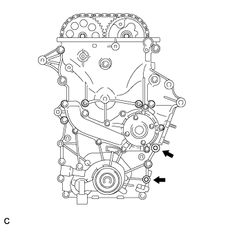
Remove the seal packing from the 2 bolt holes for the No. 1 compressor mounting bracket.
Note
Do not use any cleaners to remove the seal packing.
-
-
-
INSTALL OIL PAN SUB-ASSEMBLY
-
Install the stud bolt.
-
Using an E5 "torx" socket wrench, install the stud bolts labeled A for the oil pan as shown in the illustration.
-
Using an E7 "torx" socket wrench, install the stud bolts labeled B for the oil strainer as shown in the illustration.
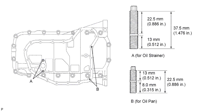
- Torque:
- for stud bolt A
- 7.5 N*m { 76 kgf*cm, 66 in.*lbf }
- for stud bolt B
- 3.0 N*m { 31 kgf*cm, 27 in.*lbf }
-
-
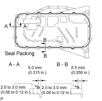
Apply seal packing in a continuous bead as shown in the illustration.
Seal packing Toyota Genuine Seal Packing Black, Three Bond 1207B or equivalent Seal width 2.0 to 3.0 mm (0.08 to 0.12 in.) Note
-
Remove any oil from the contact surface.
-
Install the crankcase within 3 minutes after applying seal packing.
-
Do not start the engine for at least 4 hours after installing.
-
-
Install a new O-ring.
-
Temporarily install the oil pan with the 16 bolts and 2 nuts.
Tech Tips
Bolt length:
20 mm (0.79 in.) for bolt A
40 mm (1.57 in.) for bolt B
-
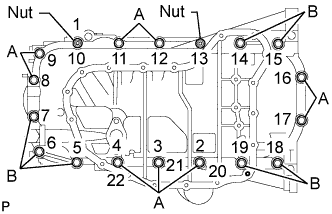
Uniformly tighten the 16 bolts and 2 nuts in the sequence shown in the illustration.
- Torque:
- 26 N*m { 265 kgf*cm, 19 ft.*lbf }
-
-
INSTALL OIL STRAINER SUB-ASSEMBLY
-
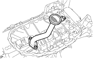
Install a new gasket and the oil strainer with the bolt and 2 nuts.
- Torque:
- 20 N*m { 204 kgf*cm, 15 ft.*lbf }
-
-
INSTALL OIL PAN SUB-ASSEMBLY NO.2
-
Apply seal packing in a continuous bead as shown in the illustration.
Seal packing Toyota Genuine Seal Packing Black, Three Bond 1207B or equivalent Seal width 2.5 to 3.5 mm (0.098 to 0.138 in.) Note
-
Remove any oil from the contact surface.
-
Install the crankcase within 3 minutes after applying seal packing.
-
Do not start the engine for at least 4 hours after installing.
-
-
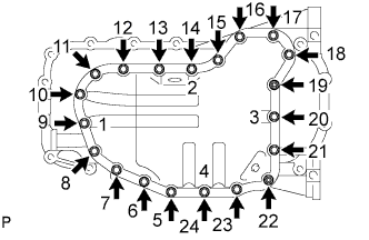
Temporarily install the oil pan with the 18 bolts and 2 nuts.
-
Uniformly tighten the 18 bolts and 2 nuts in the sequence shown in the illustration.
- Torque:
- 9.0 N*m { 92 kgf*cm, 80 in.*lbf }
-
Install a new gasket and the drain plug.
- Torque:
- 38 N*m { 382 kgf*cm, 28 ft.*lbf }
-
-
INSTALL CRANKSHAFT PULLEY
-
Align the pulley set key with the key groove of the pulley, and slide it on the pulley.
-
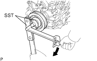
Using SST, install a new pulley bolt.
- Torque:
- 260 N*m { 2,650 kgf*cm, 192 ft.*lbf }
- SST
- 09213-54015 ( 91651-60855 )
- 09330-00021
Note
Do not reuse the pulley bolt.
-
-
INSTALL CRANKSHAFT POSITION SENSOR
-
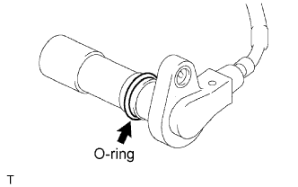
Apply engine oil to the O-ring.
-

Install the crankshaft position sensor with the bolt.
- Torque:
- 8.5 N*m { 87 kgf*cm, 75 in.*lbf }
-
-
INSTALL CYLINDER HEAD COVER SUB-ASSEMBLY
-
Apply seal packing as shown in the illustration.
-
Install the 2 gaskets to the head cover.
Seal packing Toyota Genuine Seal Packing Black, Three Bond 1207B or equivalent Note
-
Remove any oil from the contact surface.
-
Install the crankcase within 3 minutes after applying seal packing.
-
Do not start the engine for at least 4 hours after installing.
-
-

Temporarily install the cover with the 19 bolts and 2 nuts.
-
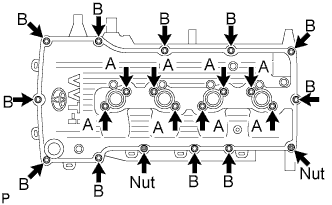
Fully tighten the bolts (A) shown in the illustration.
- Torque:
- 9.0 N*m { 92 kgf*cm, 80 in.*lbf }
-
Fully tighten the bolts (B) shown in the illustration.
- Torque:
- 9.0 N*m { 92 kgf*cm, 80 in.*lbf }
Tech Tips
Make sure the tightening torque of bolts (A).
-
-
INSTALL IGNITION COIL ASSEMBLY
-
Install the ignition coils with the bolts.
- Torque:
- 9.0 N*m { 92 kgf*cm, 80 in.*lbf }
-
-
INSTALL V-RIBBED BELT TENSIONER ASSEMBLY
-
Temporarily install the belt tensioner with the 2 bolts.
Tech Tips
-
Make sure that the belt tensioner is in contact with the engine block.
-
Check that the bolt holes of the belt tensioner and timing chain cover are aligned.
-
-
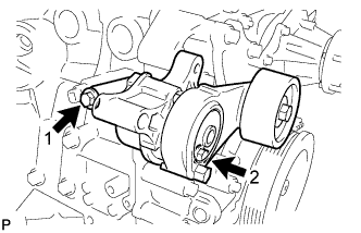
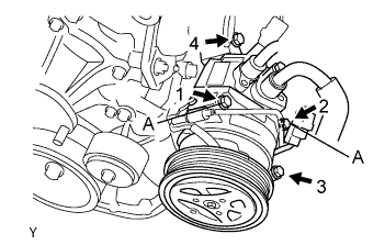
Install the tensioner by tightening the 2 bolts in the order shown in the illustration.
- Torque:
- Bolt 1
- 40 N*m { 408 kgf*cm, 30 ft.*lbf }
- Bolt 2
- 21 N*m { 214 kgf*cm, 15 ft.*lbf }
-
-
INSTALL IDLER PULLEY SUB-ASSEMBLY NO.1
-
Install the idler pulley sub-assembly No.1, collar and pulley plate with the bolt.
- Torque:
- 43 N*m { 438 kgf*cm, 32 ft.*lbf }
Note
Check that the pulley plate and collar are assembled properly to the idler pulley No.1.
-
-
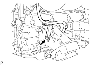
INSTALL COMPRESSOR MOUNTING BRACKET NO.1 (w/ Air Conditioning)
Note
Install the compressor mounting bracket No. 1 exactly as described in the procedures below to properly secure and prevent damage to the fan and generator V belt.
-
Temporarily install the compressor mounting bracket No. 1 with the 3 bolts.
Tech Tips
Temporarily install the compressor mounting bracket No. 1 with the 3 bolts so that the bracket can be moved by hand.
-
Push the compressor mounting bracket No. 1 toward the cylinder block as shown in the illustration and tighten bolt B.

- Torque:
- Bolt B
- 45 N*m { 459 kgf*cm, 33 ft.*lbf }
Tech Tips
Make sure there is no clearance between the cylinder block and compressor mounting bracket No. 1 as shown in the illustration.
-
Uniformly tighten the 4 bolts in the order shown in the illustration.
- Torque:
- Bolt A
- 45 N*m { 459 kgf*cm, 33 ft.*lbf }
- Bolt C
- 25 N*m { 255 kgf*cm, 18 ft.*lbf }
-
-
INSTALL GENERATOR ASSEMBLY
-
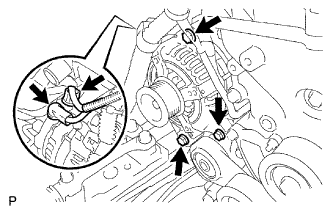
Install the generator assembly with the 3 bolts.
- Torque:
- 43 N*m { 438 kgf*cm, 32 ft.*lbf }
-
Install the generator wire with the nut to terminal B.
- Torque:
- 9.8 N*m { 100 kgf*cm, 87 in.*lbf }
-
Install the terminal cap.
-
Connect the generator connector.
-
-
INSTALL THERMOSTAT
-
Install a new gasket to the thermostat.
-
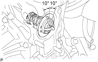
Install the thermostat with the jiggle valve upward.
Tech Tips
The jiggle valve may be set within 10° of either side of the prescribed position.
-
-
INSTALL WATER INLET
-
Install a new gasket and the water inlet with the bolt and 2 nuts.
- Torque:
- 28 N*m { 286 kgf*cm, 21 ft.*lbf }
-
-
INSTALL WATER BY-PASS PIPE NO.1
-
Install a new gasket and the water by-pass pipe with the 2 nuts and bolt.
- Torque:
- Nut
- 18 N*m { 180 kgf*cm, 13 ft.*lbf }
- Bolt
- 8.0 N*m { 80 kgf*cm, 71 in.*lbf }
-
-
INSTALL FAN PULLEY
-
Install the fan spacer and fan pulley with the 4 nuts.
- Torque:
- 25 N*m { 255 kgf*cm, 18 ft.*lbf }
-
-
INSTALL INTAKE MANIFOLD
-
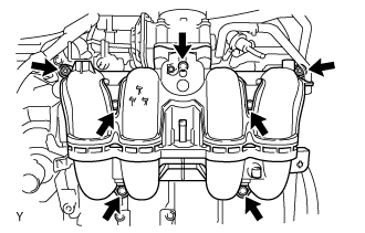
Install a new gasket and the intake manifold with the 5 bolts and 2 nuts.
- Torque:
- 25 N*m { 255 kgf*cm, 18 ft.*lbf }
-
Connect the ventilation hose No.3.
-
-
INSTALL INJECTOR ASSEMBLY
-
Apply a light coat of grease or gasoline to new O-rings and install them to the injector spacers.
Note
Make sure that the O-rings are installed between the parts correctly.
-
Install the injection spacers.
-
Apply a light coat of grease or gasoline to the place where the delivery pipe touches the O-ring.
-
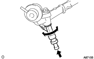
To install the fuel injector into the fuel delivery pipe, push the fuel injector while twisting it right and left.
Note
-
Be careful not to twist the O-ring.
-
After installing the fuel injector, check that it turns smoothly. If not, reinstall it with a new O-ring.
-
-
-
INSTALL FUEL DELIVERY PIPE SUB-ASSEMBLY
-
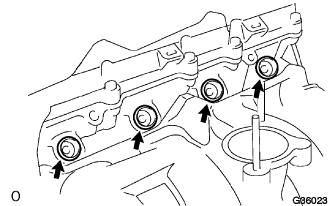
Install the 4 spacers to the cylinder head.
-
Install the delivery pipe spacers.
-
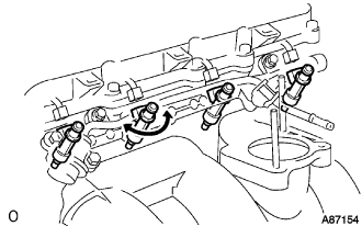
Temporarily install the 2 bolts and fuel delivery pipe together with the 4 injectors.
Note
-
Do not drop the fuel injector when installing the fuel delivery pipe.
-
Make sure that the fuel injector turns smoothly.
-
-
Fully tighten the 2 bolts.
- Torque:
- 12 N*m { 122 kgf*cm, 10 ft.*lbf }
-
Apply a light coat of grease or gasoline to the place where the delivery pipe touches the O-ring.
-
Install the 2 bolts and pressure pulsation damper assembly.
- Torque:
- 8.5 N*m { 87 kgf*cm, 75 in.*lbf }
-
Connect the 2 fuel hoses.
-
-
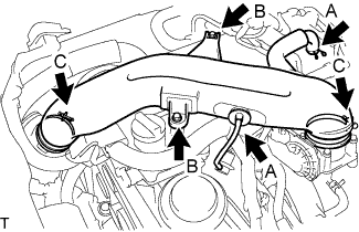
INSTALL THROTTLE WITH MOTOR BODY ASSEMBLY
-
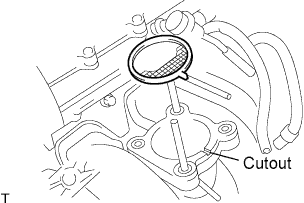
Install a new gasket onto the intake manifold.
Tech Tips
Fit the gasket to the cutout of the intake manifold.
-
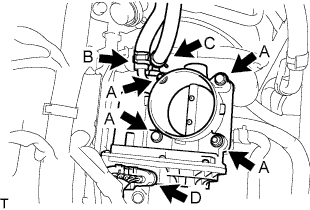
for Type A:
Install the throttle body assembly with the 2 bolts and 2 nuts. (A)
- Torque:
- 9.0 N*m { 92 kgf*cm, 80 in.*lbf }
-
for Type B:
Install the throttle body assembly with the 4 bolts. (A)
- Torque:
- 9.0 N*m { 92 kgf*cm, 80 in.*lbf }
-
Connect the water by-pass hose, and slide the clamp to secure it. (B)
-
Connect the No. 2 water by-pass hose, and slide the clamp to secure it. (C)
-
Connect the throttle motor connector. (D)
-
-
CONNECT ENGINE WIRE
-
Connect the +B terminal and connector of the starter.
- Torque:
- 9.8 N*m { 100 kgf*cm, 87 in.*lbf }
-
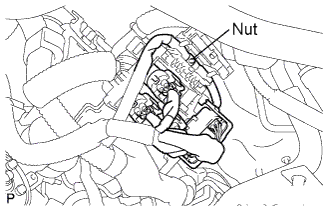
Install the connectors and nut as shown in the illustration.
-
Connect the clamps of the engine wire and earth cable.
-
Connect the connectors of the ECM.
-
Install the wire harness support of the engine ECM.
-
-
INSTALL COMPRESSOR AND MAGNETIC CLUTCH (w/ Air Conditioning)
-
Temporarily install the bolt A to install the compressor.
-
Install the compressor completely by tightening the 4 bolts in the order shown in the illustration.
- Torque:
- 25 N*m { 255 kgf*cm, 18 ft.*lbf }
Note
In order to prevent misalignment, which causes belt rattle, tightening of the bolts must be performed in the order shown.
-
Connect the suction tube clamp with the bolt.
- Torque:
- 5.4 N*m { 55 kgf*cm, 48 in.*lbf }
-
Connect the compressor connector.
-
-
INSTALL OIL LEVEL GAGE GUIDE
-
Install the gauge guide with the bolt.
- Torque:
- 20 N*m { 204 kgf*cm, 15 ft.*lbf }
-
-
INSTALL OIL LEVEL GAGE SUB-ASSEMBLY
-
INSTALL VANE PUMP ASSEMBLY
-
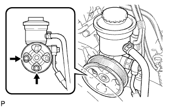
Install the vane pump with the 2 bolts.
- Torque:
- 21 N*m { 214 kgf*cm, 15 ft.*lbf }
-
Connect the PS fluid pressure switch connector.
-
-
CONNECT FUEL HOSE NO.2
-
Connect the fuel hose No.2 to the delivery pipe.
-
-
CONNECT FUEL HOSE
-
Align the connector and pipe. Push on the connector until the retainer locks with a click sound. Click here
-
Pull the connector to check that the connector is securely connected. Click here
-
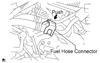
Install the connector and lock it with the fuel hose connector cover. Click here
-
-
INSTALL INTAKE AIR CONNECTOR
-
Temporarily install the intake air connector to the throttle body assembly.
-
Connect the No. 2 ventilation hose and vacuum hose, and slide the clamp to secure it. (A)
-
Install the intake air connector with the 2 bolts. (B)
- Torque:
- 8.0 N*m { 82 kgf*cm, 71 in.*lbf }
-
Tighten the 2 hose clamp bolts. (C)
- Torque:
- 5.0 N*m { 51 kgf*cm, 44 in.*lbf }
-
-
CONNECT UNION TO CONNECTOR TUBE HOSE
-
Connect the union to connector tube hose to the intake manifold.
-
-
CONNECT FUEL VAPOR FEED HOSE ASSEMBLY
-
Connect the fuel vapor feed hose to the VSV.
-
-
CONNECT RADIATOR HOSE OUTLET
-
Connect the radiator outlet hose to the clamp.
-
-
CONNECT RADIATOR HOSE INLET
-
Connect the radiator inlet hose to the clamp.
-
-
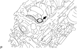
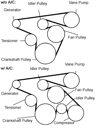
INSTALL FAN & GENERATOR V BELT
-
Install the drive belt to the pulleys except the drive belt tensioner pulley.
-
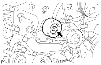
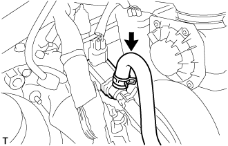
Use the hexagon-shaped part indicated by the arrow in the illustration to move the tensioner pulley downward and then install the drive belt to the tensioner pulley.
Note
-
The backside of the drive belt should face the tensioner pulley.
-
Check that the drive belt is properly set to each pulley.
-
-
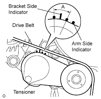
After a new belt has been installed, check that the tensioner indicator mark is within range A shown in the illustration.
-
-
INSTALL CAMSHAFT POSITION SENSOR
-
Apply engine oil to the O-ring.
-
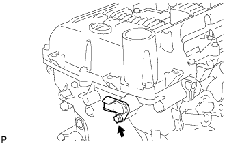
Install the camshaft position sensor with the bolt.
- Torque:
- 8.5 N*m { 87 kgf*cm, 75 in.*lbf }
-
-
INSTALL ENGINE SERVICE HOLE SUB COVER SUB-ASSEMBLY
-
Install the engine service hole sub cover with the 5 bolts.
- Torque:
- 13 N*m { 133 kgf*cm, 10 ft.*lbf }
-
-
INSTALL FRONT DOOR SCUFF PLATE RH
-
INSTALL FRONT SEAT ASSEMBLY RH (for Hi-back Seat Type)
-
Perform the same procedure as above on the opposite side. Click here
-
-
INSTALL FRONT SEAT ASSEMBLY RH (for Low-back Seat Type)
-
Perform the same procedure as above on the opposite side. Click here
-
-
CONNECT BATTERY NEGATIVE TERMINAL
-
ADD ENGINE OIL
-
ADD ENGINE COOLANT
-
Tighten the radiator drain cock plug by hand.
-
Tighten the cylinder block water drain cock plug.
- Torque:
- 13 N*m { 130 kgf*cm, 9 ft.*lbf }
-
Fill the radiator reservoir assembly with engine coolant to the top of the inlet.
Standard Capacity Item Specified Condition w/o Rear Heater 11.2 liters (11.8 US qts, 9.9 Imp. qts) w/ Rear Heater 13.2 liters (13.9 US qts, 11.6 Imp. qts) Note
Never use water as a substitute for engine coolant.
Tech Tips
TOYOTA vehicles are filled with TOYOTA SLLC at the factory. In order to avoid damage to the engine cooling system and other technical problems, only use TOYOTA SLLC or similar high quality ethylene glycol based non-silicate, non-amine, non-nitrite, non-borate coolant with long-life hybrid organic acid technology (coolant with long-life hybrid organic acid technology is a combination of low phosphates and organic acids).
-
Remove the 2-way that is located near the throttle body assembly.
-
When air is bled and the engine coolant drains out, install the 2-way.
-
Add coolant through the radiator reservoir assembly filler opening until the coolant reaches the B line and install the radiator reservoir cap sub-assembly. [*1]
-
Warm up the engine until the thermostat opens. While the thermostat is open, circulate the coolant for several minutes. [*2]
CAUTION:
-
Wear protective gloves.
-
Be careful as the radiator hoses are hot.
-
Keep your hands away from the radiator fans.
Note
-
Immediately after starting the engine, if the radiator reservoir assembly does not have any engine coolant, perform the following: 1) stop the engine, 2) wait until the engine coolant has cooled down, and 3) add engine coolant.
-
Do not start the engine when there is no engine coolant in the radiator reservoir assembly.
-
Make sure that the needle does not show an abnormally high temperature.
-
If there is not enough engine coolant, the engine may overheat.
Tech Tips
-
Press the No. 2 and No. 3 radiator hoses several times by hand, and then check the level of the engine coolant.
-
The thermostat open timing can be confirmed by pressing the No. 3 radiator hose by hand, and checking when the engine coolant starts to flow inside the hose.
-
-
Stop the engine, and wait until the engine coolant cools down to ambient temperature. [*3]
-
Check the engine coolant level in the radiator reservoir assembly. [*4]
Tech Tips
-
If the engine coolant level is below the LOW line, repeat step *1 through *4.
-
If the engine coolant level is above the FULL line, drain engine coolant until the engine coolant level is between the FULL and LOW lines.
-
-
-
CHECK FOR FUEL LEAKS
-
CHECK FOR ENGINE OIL LEAKS
-
CHECK FOR ENGINE COOLANT LEAKS
-
INSTALL ENGINE UNDER COVER NO.2 (w/ Engine Under Cover No.2)
-
Install the engine under cover No.2 together with the engine side under cover LH and engine side under cover RH (for Wide Body).
- Torque:
- 13 N*m { 133 kgf*cm, 10 ft.*lbf }
-
-
INSTALL ENGINE UNDER COVER NO.1 (w/ Engine Under Cover No.1)
- Torque:
- 13 N*m { 133 kgf*cm, 10 ft.*lbf }
-
INSPECT CHECK IDLE SPEED AND IGNITION TIMING
-
Warm up and stop the engine.
Note
A warmed up engine should have an engine coolant temperature of over 80°C (176°F), have an engine oil temperature of 60°C (140°F), and the engine rpm should be stabilized.
-
When using the intelligent tester:
-
Connect the intelligent tester to the DLC3.
-
Start the engine and idle it.
-
Turn the intelligent tester main switch on.
-
Enter the following items:
Powertrain / Engine and ECT / Data list / IGN Advance
Ignition timing 5 to 15° BTDC at idle Tech Tips
Refer to the intelligent tester operator's manual for further detail.
-
-
When not using the intelligent tester:
-
Connect the tester probe of a timing light to the wire of the ignition coil connector for the No.4 cylinder.
Note
-
Use a timing light that detects the first signal.
-
After checking, be sure to wrap the wire harness with tape.
-
-
Turn the ignition switch to the ON position.
-
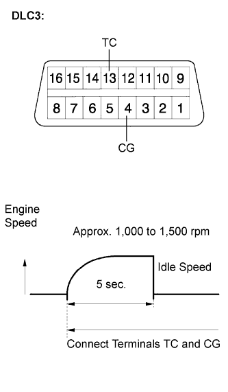
Using SST, connect terminals 13 (TC) and 4 (CG) of the DLC3.
- SST
- 09843-18040
Note
-
Confirm the terminal numbers before connecting them. Connecting the wrong terminals can damage the engine.
-
When checking the ignition timing, the transmission should be in the neutral.
Tech Tips
-
After connecting terminals (TC and CG), engine rpm changes to approximately 1,000 to 1,500 rpm for 5 seconds, then returns to idle speed. This is because the ECM checks that the ISC (idle speed control system) operates properly.
-
Perform the inspection of the ignition timing after engine rpm is returned to idle speed.
-
Inspect the ignition timing
Ignition timing 3 to 7° BTDC at idle -
Disconnect terminals 13 (TC) and 4 (CG) of the DLC3.
-
Inspect the ignition timing
Ignition timing 5 to 15° BTDC at idle -
Check that the ignition timing advances immediately when the engine speed is increased.
-
Turn the ignition switch off.
-
Remove the timing light.
-
-
-
CHECK FUNCTION OF THROTTLE BODY
-
INSPECT ABS SENSOR SIGNAL
-
PERFORM INITIALIZATION