ECD SYSTEM, Diagnostic DTC:P0500
| DTC Code | DTC Name |
|---|---|
| P0500 | Vehicle Speed Sensor |
DESCRIPTION
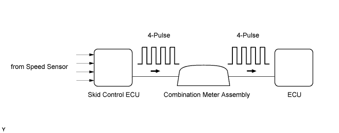
Vehicles, which are equipped with ABS (Anti-lock Brake System), detect the vehicle speed using the skid control ECU (brake actuator assembly) and speed sensor. The speed sensor monitors the wheel rotation speed and sends a signal to the skid control ECU. The skid control ECU converts the wheel speed signal into a 4-pulse signal and transmits it to the ECM via the combination meter assembly. The ECM determines the vehicle speed based on the frequency of the pulse signal.
Tech Tips
-
Various systems use the vehicle speed signal distributed from the combination meter assembly. Check all the components possibly related to the speed signal.
-
A voltage of 12 V or 5 V is output from each ECU and then input to the combination meter assembly. The signal is changed to a pulse signal at the transistor in the combination meter assembly. Each ECU controls the respective system based on the pulse signal.
-
If a short occurs in any of the ECUs or in the wire harness connected to an ECU, all systems using the speed signal will not operate normally.
| DTC Detection Drive Pattern | DTC Detection Condition | Trouble Area |
|---|---|---|
| Drive the vehicle at 10 km/h (6.3 mph) or more | Conditions (a) and (b) are met for 5 seconds or more (2 trip detection logic): (a) While vehicle being driven. (b) No vehicle speed sensor signal transmitted to ECM. |
|
| DTC No. | Data List |
|---|---|
| P0500 | Vehicle Speed |
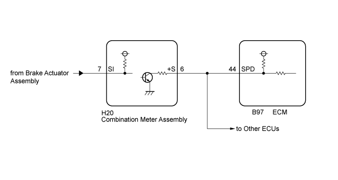
WIRING DIAGRAM
INSPECTION PROCEDURE
Note
After replacing the ECM, the new ECM needs registration Click here and initialization Click here.
Tech Tips
Read freeze frame data using the GTS. Freeze frame data records the engine condition when malfunctions are detected. When troubleshooting, freeze frame data can help determine if the vehicle was moving or stationary, if the engine was warmed up or not, and other data from the time the malfunction occurred.
PROCEDURE
-
READ VALUE USING GTS (VEHICLE SPEED)
-
Connect the GTS to the DLC3.
-
Start the engine and turn the GTS on.
-
Enter the following menus: Powertrain / Engine and ECT / Data List / Vehicle Speed.
-
Drive the vehicle.
-
Read the value displayed on the GTS.
Result Result Proceed to Values displayed on GTS and speedometer display not equal A Values displayed on GTS and speedometer display equal B
B 
CHECK INTERMITTENT PROBLEMS
A 
-
-
CHECK HARNESS AND CONNECTOR (COMBINATION METER ASSEMBLY - ECM)
-
Disconnect the combination meter assembly connector.
-
Disconnect the ECM connector.
-
Measure the resistance according the value(s) in the table below.
Standard Resistance Tester Connection Condition Specified Condition H20-6 (+S) - B97-44 (SPD) Always Below 1 Ω H20-6 (+S) or B97-44 (SPD) - Body ground and other terminals Always 10 kΩ or higher -
Reconnect the combination meter assembly connector.
-
Reconnect the ECM connector.
NG
REPAIR OR REPLACE HARNESS OR CONNECTOR
OK
-
-
CHECK COMBINATION METER SYSTEM
-
Check the circuits that send vehicle speed signals to this system in the combination meter system Click here.
NEXT
-
-
CONFIRM WHETHER MALFUNCTION HAS BEEN SUCCESSFULLY REPAIRED
-
Connect the GTS to the DLC3.
-
Clear the DTCs Click here.
-
Turn the ignition switch off for 30 seconds or more.
-
Turn the ignition switch to ON and turn the GTS on.
-
Start the engine.
-
Drive the vehicle at 10 km/h (6.3 mph) or more.
-
Enter the following menus: Powertrain / Engine and ECT / Trouble Codes.
-
Confirm that the pending DTC is not output again.
NEXT 
END
-