ECD SYSTEM, Diagnostic DTC:P0100
| DTC Code | DTC Name |
|---|---|
| P0100 | Mass Air Flow Circuit |
DESCRIPTION
The mass air flow meter sub-assembly is a sensor that measures the intake air volume using the following built-in components:
-
By-pass duct (allows some of the intake air to flow past a silicon chip sensor).
-
Silicon chip sensor (uses a heater control bridge circuit and temperature sensor bridge circuit to detect the difference in the temperature of the intake air that passes the sensors positioned before and after the heater).
-
Control circuit (converts the difference in temperature into a pulse signal and performs correction).
Intake air flows past the temperature sensor (before heater), the heater, and then the temperature sensor (after heater) of the silicon chip sensor in the by-pass duct. As the intake air is warmed up when it is exposed to the heater, the temperature of the intake air as it flows past the temperature sensor (after heater) is higher than when it flows past the temperature sensor (before heater). The difference in temperature of the intake air at each temperature sensor varies depending on the velocity of the intake air that flows past the silicon chip sensor. The temperature sensor bridge circuit detects the difference in temperature and the control circuit converts it into a pulse signal and outputs it to the ECM. When the temperature detected by the temperature sensor (before heater) is higher than that detected by the temperature sensor (after heater), backflow of the intake air is detected.
The ECM calculates the intake air volume based on the pulse signal received from the mass air flow meter sub-assembly.
The heater control bridge circuit has a temperature sensor and power transistor, and maintains the heater temperature at a specific temperature.
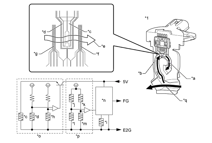
| *1 | Mass Air Flow Meter Sub-assembly | - | - |
| *a | Silicon Chip Sensor | *b | By-pass Duct |
| *c | Heater | *d | Heater Thermistor |
| *e | Intake Air | *f | Temperature Sensor (After Heater) |
| *g | Temperature Sensor (Before Heater) | *h | Intake Air Thermistor 1 |
| *i | Intake Air Thermistor 2 | *j | Temperature Sensor (Before Heater) 1 |
| *k | Temperature Sensor (After Heater) 2 | *l | Temperature Sensor (After Heater) 1 |
| *m | Temperature Sensor (Before Heater) 2 | *n | Control Circuit |
| *o | Heater Control Bridge Circuit | *p | Temperature Sensor Bridge Circuit |
| *q | Air Flow | - | - |
| DTC Detection Drive Pattern | DTC Detection Condition | Trouble Area |
|---|---|---|
| 3 seconds after engine is started | Mass air flow meter sub-assembly signal frequency is less than 0.1 kHz with the engine speed at 400 rpm or more for 3 seconds (1 trip detection logic). |
|
| DTC No. | Data List |
|---|---|
| P0100 | MAF |
Tech Tips
-
If DTC P0100 is stored, the following symptoms may appear (as the ECM mistakenly determines that there is less air than the actual intake air amount, EGR is decreased according to the target EGR):
-
Combustion noise worsens
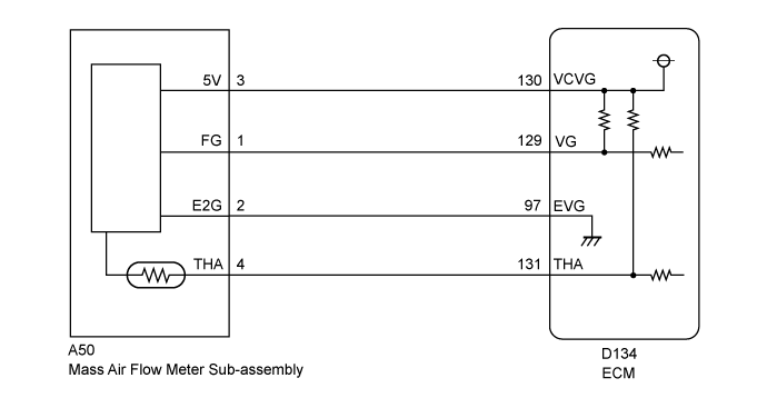
WIRING DIAGRAM
INSPECTION PROCEDURE
Note
After replacing the ECM, the new ECM needs registration Click here and initialization Click here.
Tech Tips
Read freeze frame data using the GTS. Freeze frame data records the engine condition when malfunctions are detected. When troubleshooting, freeze frame data can help determine if the vehicle was moving or stationary, if the engine was warmed up or not, and other data from the time the malfunction occurred.
PROCEDURE
-
CHECK MASS AIR FLOW METER SUB-ASSEMBLY (POWER SOURCE OF MASS AIR FLOW METER SUB-ASSEMBLY)
-
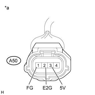
Text in Illustration *a Front view of wire harness connector
(to Mass Air Flow Meter Sub-assembly)
Disconnect the mass air flow meter sub-assembly connector.
-
Turn the ignition switch to ON.
-
Measure the voltage according to the value(s) in the table below.
Standard Voltage Tester Connection Switch Condition Specified Condition A50-3 (5V) - Body ground Ignition switch ON 4.8 to 5.2 V A50-1 (FG) - A50-2 (E2G) Ignition switch ON 4.8 to 5.2 V -
Reconnect the mass air flow meter sub-assembly connector.
NG 
CHECK HARNESS AND CONNECTOR (MASS AIR FLOW METER SUB-ASSEMBLY - ECM) Click here
OK 
-
-
REPLACE MASS AIR FLOW METER SUB-ASSEMBLY
-
Replace the mass air flow meter sub-assembly Click here.
NEXT
-
-
CHECK IF DTC RECURS (SEE IF DTC P0100 IS OUTPUT AGAIN)
-
Connect the GTS to the DLC3.
-
Turn the ignition switch to ON and turn the GTS on.
-
Clear the DTCs Click here.
-
Turn the ignition switch off and wait for at least 30 seconds.
-
Turn the ignition switch to ON and turn the GTS on.
-
Start the engine and wait for 3 seconds or more.
-
Enter the following menus: Powertrain / Engine and ECT / Trouble Codes.
-
Read the DTCs.
Result Result Proceed to DTC P0100 is output A DTCs are not output B
B 
END
A
-
-
REPLACE ECM
-
Replace the ECM Click here.
NEXT
CONFIRM WHETHER MALFUNCTION HAS BEEN SUCCESSFULLY REPAIRED Click here
-
-
CHECK HARNESS AND CONNECTOR (MASS AIR FLOW METER SUB-ASSEMBLY - ECM)
-
Disconnect the mass air flow meter sub-assembly connector.
-
Disconnect the ECM connector.
-
Measure the resistance according to the value(s) in the table below.
Standard Resistance Tester Connection Condition Specified Condition A50-3 (5V) - D134-130 (VCVG) Always Below 1 Ω A50-1 (FG) - D134-129 (VG) Always Below 1 Ω A50-2 (E2G) - D134-97 (EVG) Always Below 1 Ω A50-3 (5V) or D134-130 (VCVG) - Body ground and other terminals Always 10 kΩ or higher A50-1 (FG) or D134-129 (VG) - Body ground and other terminals Always 10 kΩ or higher A50-2 (E2G) or D134-97 (EVG) - Body ground and other terminals Always 10 kΩ or higher -
Reconnect the mass air flow meter sub-assembly connector.
-
Reconnect the ECM connector.
NG
REPAIR OR REPLACE HARNESS OR CONNECTOR Click here
OK
-
-
REPLACE ECM
-
Replace the ECM Click here.
NEXT
CONFIRM WHETHER MALFUNCTION HAS BEEN SUCCESSFULLY REPAIRED Click here
-
-
REPAIR OR REPLACE HARNESS OR CONNECTOR
-
Repair or replace the harness or connector.
NEXT
-
-
CONFIRM WHETHER MALFUNCTION HAS BEEN SUCCESSFULLY REPAIRED
-
Connect the GTS to the DLC3.
-
Turn the ignition switch to ON and turn the GTS on.
-
Clear the DTCs Click here.
-
Turn the ignition switch off and wait for at least 30 seconds.
-
Turn the ignition switch to ON and turn the GTS on.
-
Start the engine and wait for 3 seconds or more.
-
Enter the following menus: Powertrain / Engine and ECT / Trouble Codes.
-
Confirm that the DTC is not output again.
NEXT 
END
-