ECD SYSTEM (w/ DPF) VC Output Circuit
DESCRIPTION
The ECM constantly generates 5 V of power from the battery voltage supplied to the +B (BATT) terminal to operate the microprocessor. The ECM also provides this power to the sensors through the VC output circuit.
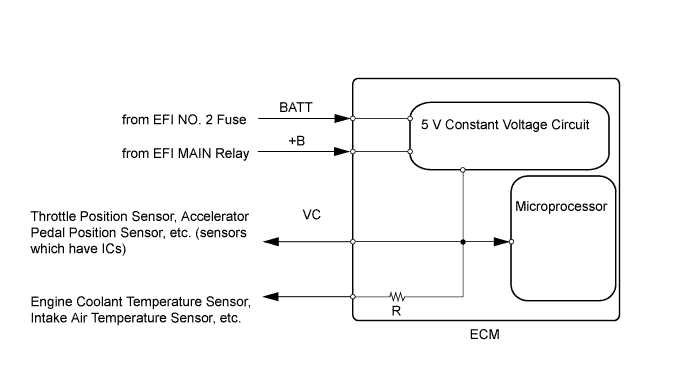
When the VC circuit is short-circuited, the microprocessor in the ECM and sensors that are supplied with power through the VC circuit are inactivated because the power is not supplied from the VC circuit. Under this condition, the system does not start up and the MIL does not illuminate even if the system malfunctions.
Tech Tips
Under normal conditions, the MIL is illuminated for several seconds when the ignition switch is first turned to ON. The MIL goes off when the engine is started.
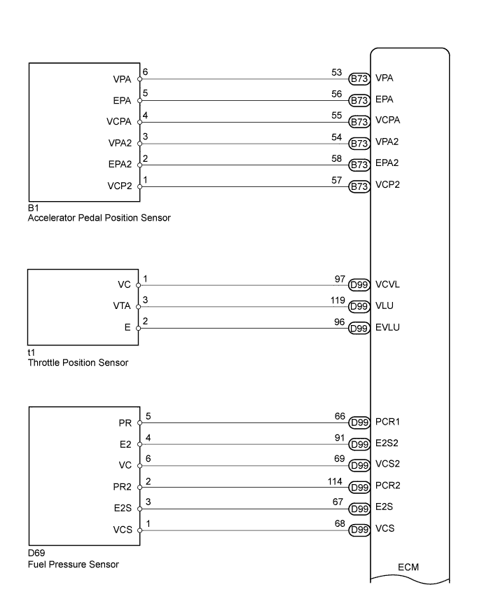
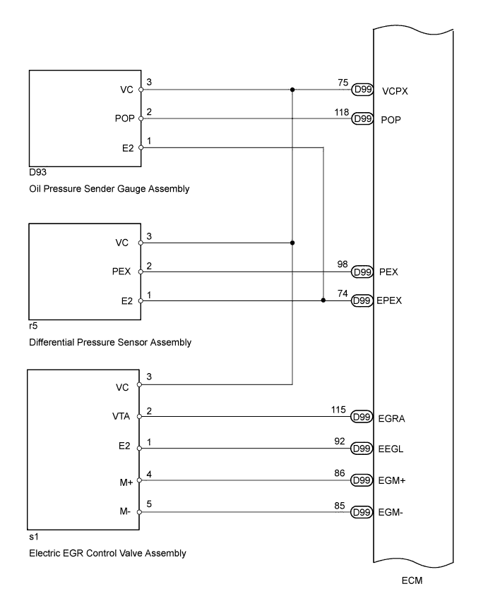
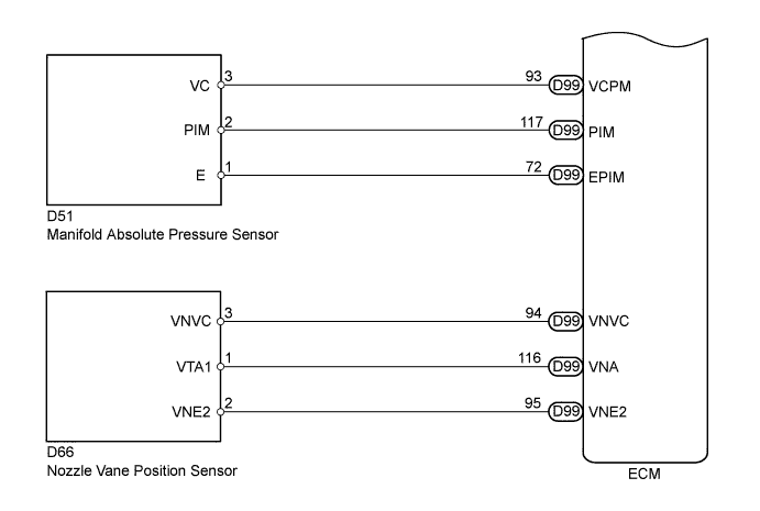
WIRING DIAGRAM
-
For the circuit diagram of the ECM power source circuit.
-
VC output Circuit
INSPECTION PROCEDURE
Note
-
Inspect the fuses of circuits related to this system before performing the following inspection procedure.
-
After replacing the ECM, the new ECM needs registration Click here and initialization Click here.
-
After replacing the fuel supply pump assembly, the ECM needs initialization Click here.
-
After replacing an injector assembly, the ECM needs registration Click here.
PROCEDURE
-
CHECK COMMUNICATION BETWEEN GTS AND ECM
-
Connect the GTS to the DLC3.
-
Turn the Ignition switch to ON.
-
Turn the GTS on.
-
Check the communication between the GTS and ECM.
Result Result Proceed to Communication is possible A Communication is not possible B
A 
PROCEED TO NEXT SUSPECTED AREA SHOWN IN PROBLEM SYMPTOMS TABLE Click here
B 
-
-
CHECK EFI NO. 3 FUSE VOLTAGE
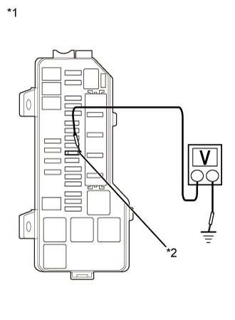
Text in Illustration *1 No. 1 Integration Relay *2 EFI NO. 3 FUSE
-
Turn the Ignition switch to ON.
-
Measure the voltage according to the value(s) in the table below.
Result Tester Connection Condition Specified Condition 2 (EFI NO.3) - Body ground Ignition switch ON 11 to 14 V Tech Tips
If the result is not as specified, since current is not flowing to the 2 (EFI NO. 3) terminals of the ECM, the system may not be started.
NG
GO TO ECM POWER SOURCE CIRCUIT Click here
OK
-
-
CHECK CONNECTION BETWEEN GTS AND ECM (ACCELERATOR PEDAL POSITION SENSOR)
-
Disconnect the accelerator pedal position sensor connector.
-
Turn the Ignition switch ON.
-
Turn the GTS on.
-
Check the communication between the GTS and ECM.
Tech Tips
It can be checked using the "Engine" item of the Data List.
Result Result Proceed to Communication is possible A Communication is not possible B -
Reconnect the accelerator pedal position sensor connector.
A
REPLACE ACCELERATOR PEDAL ROD ASSEMBLY Click here
B
-
-
CHECK CONNECTION BETWEEN GTS AND ECM (THROTTLE POSITION SENSOR)
-
Disconnect the throttle position sensor connector.
-
Turn the Ignition switch to ON.
-
Turn the GTS on.
-
Check the communication between the GTS and ECM.
Tech Tips
It can be checked using the "Engine" item of the Data List.
Result Result Proceed to Communication is possible A Communication is not possible B -
Reconnect the throttle position sensor connector.
A
REPLACE DIESEL THROTTLE BODY ASSEMBLY Click here
B
-
-
CHECK CONNECTION BETWEEN GTS AND ECM (FUEL PRESSURE SENSOR)
-
Disconnect the fuel pressure sensor connector.
-
Turn the Ignition switch to ON.
-
Turn the GTS on.
-
Check the communication between the GTS and ECM.
Tech Tips
It can be checked using the "Engine" item of the Data List.
Result Result Proceed to Communication is possible A Communication is not possible B -
Reconnect the fuel pressure sensor connector.
A
REPLACE COMMON RAIL ASSEMBLY Click here
B
-
-
CHECK CONNECTION BETWEEN GTS AND ECM (ELECTRIC EGR CONTROL VALVE ASSEMBLY)
-
Disconnect the electric EGR control valve assembly connector.
-
Turn the Ignition switch to ON.
-
Turn the GTS on.
-
Check the communication between the GTS and ECM.
Tech Tips
It can be checked using the "Engine" item of the Data List.
Result Result Proceed to Communication is possible A Communication is not possible B -
Reconnect the electric EGR control valve assembly connector.
A
REPLACE ELECTRIC EGR CONTROL VALVE ASSEMBLY Click here
B
-
-
CHECK CONNECTION BETWEEN GTS AND ECM (OIL PRESSURE SENDER GAUGE ASSEMBLY)
-
Disconnect the oil pressure sender gauge assembly connector.
-
Turn the Ignition switch to ON.
-
Turn the GTS on.
-
Check the communication between the GTS and ECM.
Tech Tips
It can be checked using the "Engine" item of the Data List.
Result Result Proceed to Communication is possible A Communication is not possible B -
Reconnect the oil pressure sender gauge assembly connector.
A
REPLACE OIL PRESSURE SENDER GAUGE ASSEMBLY Click here
B
-
-
CHECK CONNECTION BETWEEN GTS AND ECM (DIFFERENTIAL PRESSURE SENSOR ASSEMBLY)
-
Disconnect the differential pressure sensor assembly connector.
-
Turn the Ignition switch to ON.
-
Turn the GTS on.
-
Check the communication between the GTS and ECM.
Tech Tips
It can be checked using the "Engine" item of the Data List.
Result Result Proceed to Communication is possible A Communication is not possible B -
Reconnect the differential pressure sensor assembly connector.
A
REPLACE DIFFERENTIAL PRESSURE SENSOR ASSEMBLY Click here
B
-
-
CHECK CONNECTION BETWEEN GTS AND ECM (MANIFOLD ABSOLUTE PRESSURE SENSOR)
-
Disconnect the manifold absolute pressure sensor connector.
-
Turn the Ignition switch to ON.
-
Turn the GTS on.
-
Check the communication between the GTS and ECM.
Tech Tips
It can be checked using the "Engine" item of the Data List.
Result Result Proceed to Communication is possible A Communication is not possible B -
Reconnect the manifold absolute pressure sensor connector.
A
REPLACE MANIFOLD ABSOLUTE PRESSURE SENSOR
B
-
-
CHECK CONNECTION BETWEEN GTS AND ECM (NOZZLE VANE POSITION SENSOR)
-
Disconnect the nozzle vane position sensor connector.
-
Turn the Ignition switch to ON.
-
Turn the GTS on.
-
Check the communication between the GTS and ECM.
Tech Tips
It can be checked using the "Engine" item of the Data List.
Result Result Proceed to Communication is possible A Communication is not possible B -
Reconnect the nozzle vane position sensor connector.
A
REPLACE TURBOCHARGER SUB-ASSEMBLY Click here
B
-
-
CHECK HARNESS AND CONNECTOR
-
Disconnect the accelerator pedal position sensor connector.
-
Disconnect the throttle position sensor connector.
-
Disconnect the fuel pressure sensor connector.
-
Disconnect the electric EGR control valve assembly connector.
-
Disconnect the oil pressure sender gauge assembly connector.
-
Disconnect the differential pressure sensor assembly connector.
-
Disconnect the nozzle vane position sensor connector.
-
Disconnect the manifold absolute pressure sensor connector.
-
Disconnect the ECM connectors.
-
Measure the resistance according to the value(s) in the table below.
Standard Resistance Tester Connection Condition Specified Condition B73-55 (VCPA) - Body ground Always 10 kΩ or higher B73-57 (VCP2) - Body ground Always 10 kΩ or higher D99-97 (VCVL) - Body ground Always 10 kΩ or higher D99-69 (VCS2) - Body ground Always 10 kΩ or higher D99-68 (VCS) - Body ground Always 10 kΩ or higher D99-75 (VCPX) - Body ground Always 10 kΩ or higher D99-93 (VCPM) - Body ground Always 10 kΩ or higher D99-94 (VNVC) - Body ground Always 10 kΩ or higher B73-1 (+B) - Body ground Always 10 kΩ or higher B73-20 (+B2) - Body ground Always 10 kΩ or higher -
Reconnect the accelerator pedal position sensor connector.
-
Reconnect the throttle position sensor connector.
-
Reconnect the fuel pressure sensor connector.
-
Reconnect the electric EGR control valve assembly connector.
-
Reconnect the oil pressure sender gauge assembly connector.
-
Reconnect the differential pressure sensor assembly connector.
-
Reconnect the nozzle vane position sensor connector.
-
Reconnect the manifold absolute pressure sensor connector.
-
Reconnect the ECM connectors.
NG
REPAIR OR REPLACE HARNESS OR CONNECTOR
OK 
REPLACE ECM Click here
-