OIL PUMP (w/o DPF) REMOVAL

Note
-
When replacing the injectors (including shuffling the injectors between the cylinders), common rail or cylinder head, it is necessary to replace the injection pipes with new ones.
-
When replacing the fuel supply pump, common rail, cylinder block, cylinder head, cylinder head gasket or timing gear case, it is necessary to replace the fuel inlet pipe with a new one.
-
REMOVE ENGINE ASSEMBLY
-
INSTALL ENGINE STAND
-
REMOVE VANE PUMP ASSEMBLY
-

Remove the 2 nuts and the vane pump assembly.
-
Remove the vane pump O-ring from the vane pump assembly.
-
-
REMOVE TIMING GEAR COVER INSULATOR
-
Remove the bolt and timing gear cover insulator.
-
-
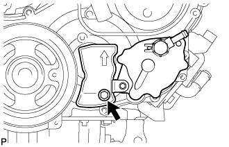
REMOVE VACUUM PUMP ASSEMBLY
-
Remove the 2 nuts, vacuum pump and 2 O-rings.
-
-
REMOVE NO. 1 TIMING BELT COVER
-
Remove the wire harness clamp.
-
Remove the 6 bolts, 6 washers and timing belt cover.
-
-
REMOVE TIMING BELT
-
REMOVE CRANKSHAFT POSITION SENSOR
-
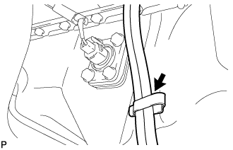
Disconnect the crankshaft position sensor connector.
-
Separate the connector from the No. 1 vacuum pipe .
-
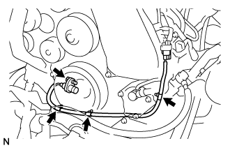
Separate the 3 wire harness clamps.
-
Remove the bolt and the crankshaft position sensor.
-
-
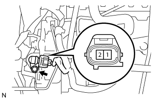
REMOVE CAMSHAFT POSITION SENSOR
-
Disconnect the camshaft position sensor connector.
-
Remove the bolt and the camshaft position sensor.
-
-
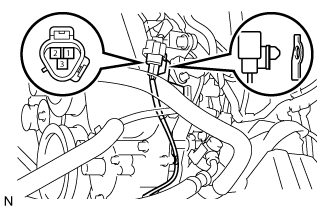
REMOVE DIESEL THROTTLE BODY ASSEMBLY
-
w/o DPF:
-
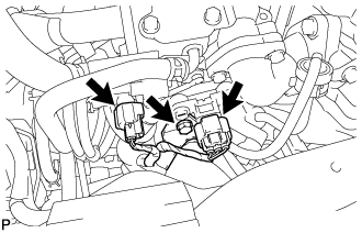
Disconnect the diesel turbo pressure sensor connector and vacuum switching valve connector.
-
Remove the bolt and disconnect the wire harness clamp.
-
-
Disconnect the 2 diesel throttle body connectors.
-
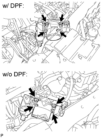
Remove the 2 bolts, 2 nuts, diesel throttle body and gasket.
-
-
REMOVE ELECTRIC EGR CONTROL VALVE ASSEMBLY
-
REMOVE EGR COOLER ASSEMBLY
-
REMOVE COMMON RAIL ASSEMBLY
-
REMOVE FUEL SUPPLY PUMP ASSEMBLY
-
REMOVE INJECTOR ASSEMBLY
-
REMOVE CAMSHAFT TIMING PULLEY
-
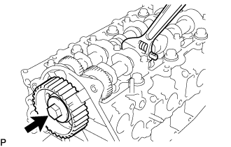
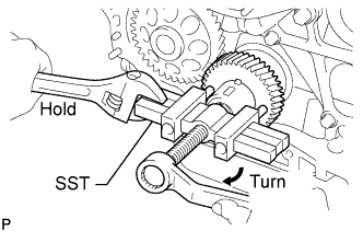
Remove the bolt and camshaft timing pulley while holding the camshaft with a wrench.
-
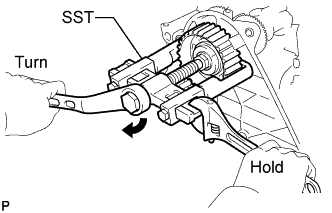
Using SST, remove the camshaft timing pulley and set key.
- SST
- 09950-40011 ( 09951-04010, 09952-04010, 09953-05010, 09957-04010 )
- 09955-04150
-
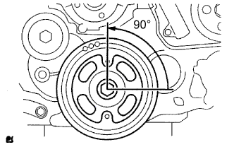
Rotate the crankshaft approximately 90° counterclockwise from TDC to lower the piston.
-
-
REMOVE NO. 2 TIMING BELT COVER
-
Remove the nut, 4 bolts and No. 2 timing belt cover.
-
-
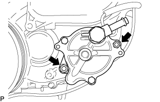
REMOVE WATER PUMP ASSEMBLY
-
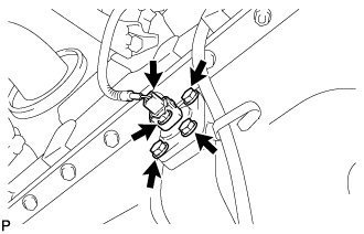
Remove the 5 bolts, 2 nuts and water pump assembly.
-
-
REMOVE CRANKSHAFT PULLEY
-
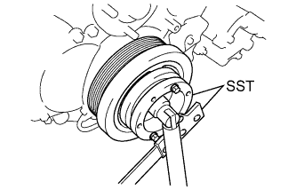
Using SST, remove the pulley bolt.
- SST
- 09213-58014
- 09330-00021
-
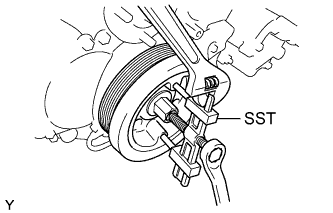
Using SST, remove the crankshaft pulley.
- SST
- 09950-50013 ( 09951-05010, 09952-05010, 09953-05020, 09954-05021 )
Note
Apply oil or grease to the threads and tip of SST (center bolt) before using it.
-
-
REMOVE ENGINE OIL LEVEL SENSOR
-
Disconnect the engine oil level sensor connector.
-
Remove the 4 bolts and engine oil level sensor.
-
-
REMOVE OIL PAN SUB-ASSEMBLY
-
Disconnect the vinyl tube from the oil pan.
-
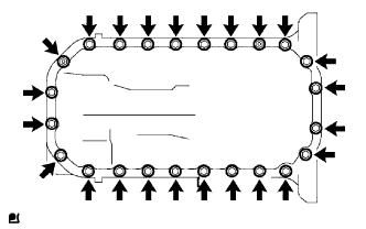
Remove the 22 bolts and 2 nuts.
-
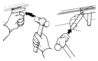
Insert the blade of an oil pan seal cutter between the oil pan and cylinder block stiffening plate, cut through the applied sealer, and then remove the oil pan and cylinder block stiffening plate.
Note
-
Do not use an oil pan seal cutter for the timing gear case side and rear oil seal retainer.
-
Be careful not to damage the oil pan flange.
-
-
-
REMOVE OIL STRAINER SUB-ASSEMBLY
-
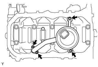
Remove the 2 bolts, 2 nuts, oil strainer and gasket.
-
-
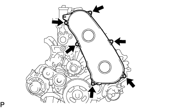
REMOVE TIMING GEAR COVER
Note
As the fuel supply pump is not installed, the injection gear is loose inside the timing gear case. Do not allow the injection gear to fall.
Tech Tips
To prevent the injection gear from falling, temporarily install the fuel supply pump.
-
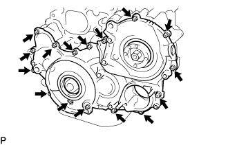
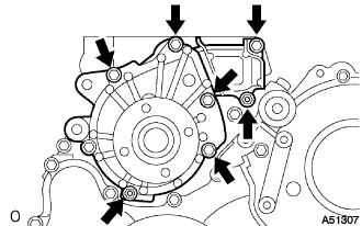
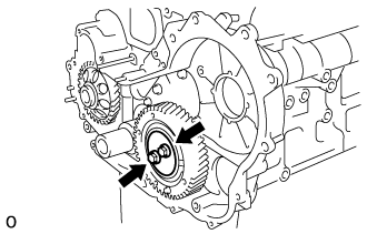
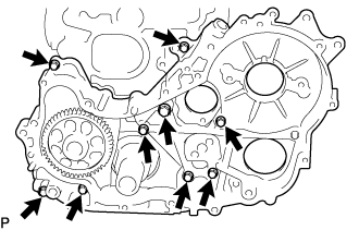
Remove the 14 bolts and 2 nuts.
-
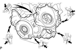
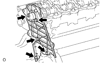
Pry the timing gear cover at the locations shown in the illustration and remove the timing gear cover.
Note
Do not damage the contact surface.
-
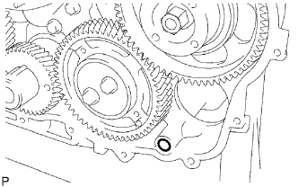
Remove the O-ring from the timing gear case.
-
Secure the No. 2 idle sub gear to the No. 1 idle gear with a service bolt.
-
-
REMOVE TIMING CHAIN OR BELT COVER OIL SEAL
-
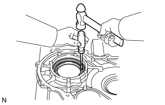
Using a screwdriver and hammer, tap out the oil seal.
-
-
REMOVE TIMING GEAR CASE OR TIMING CHAIN CASE OIL SEAL
-
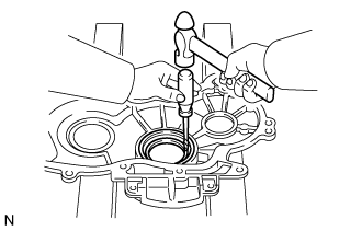
Using a screwdriver and hammer, tap out the oil seal.
-
-
REMOVE NO. 1 CRANKSHAFT POSITION SENSOR PLATE
-
Remove the No. 1 crankshaft position sensor plate.
-
-
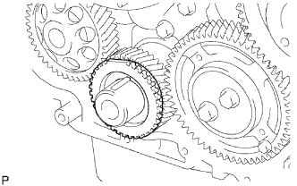
REMOVE INJECTION GEAR
-
Remove the injection gear.
-
-
REMOVE CRANKSHAFT TIMING GEAR
-
Using SST, remove the crankshaft timing gear.
- SST
- 09950-50013 ( 09951-05010, 09952-05010, 09953-05010, 09954-05011 )
-
-
REMOVE IDLE GEAR THRUST PLATE
-
Remove the 2 bolts and idle gear thrust plate.
-
-
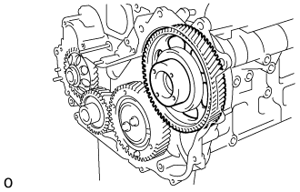
REMOVE NO. 1 IDLE GEAR
-
Remove the No. 1 idle gear together with the No. 2 idle sub gear.
Note
Make sure that the No. 2 idle sub gear and No. 1 idle gear are correctly fitted to each other.
-
-
REMOVE NO. 1 IDLE GEAR SHAFT
-
Remove the No. 1 idle gear shaft.
-
-
REMOVE TIMING GEAR CASE ASSEMBLY
-
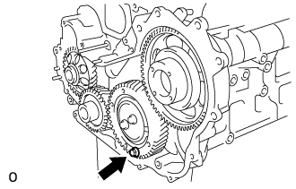
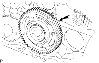
Remove the union bolt and 8 bolts.
-
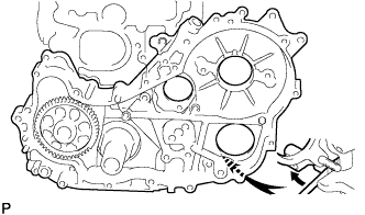
Pry the timing gear case at the location shown in the illustration and remove the timing gear case.
Note
Do not drop the driven rotor.
-
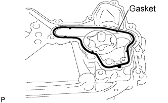
Remove the gasket from the timing gear case.
-
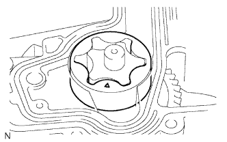
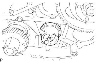
Remove the driven rotor from the timing gear case.
-
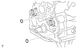
Remove the 2 O-rings from the cylinder block.
-