OIL PUMP INSTALLATION

-
INSTALL TIMING CHAIN CASE ASSEMBLY AND ENGINE WATER PUMP ASSEMBLY
-
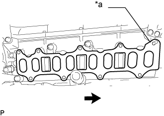
Install a new No. 2 water pump gasket.
-
Install the 4 O-rings to the cylinder block sub-assembly and cylinder head sub-assembly.
-
Clean and degrease the contact surfaces of the timing chain case assembly, cylinder head sub-assembly and cylinder block sub-assembly.
-
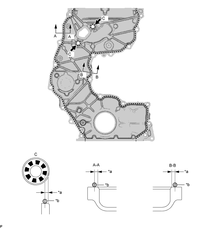
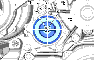
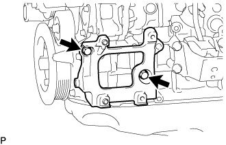
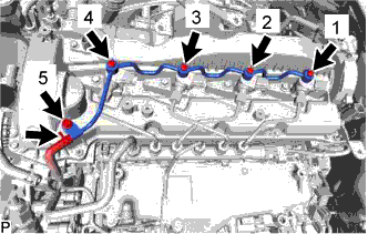
Apply a coating of seal packing to the timing chain case assembly at the points shown in the illustration.
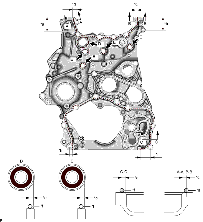
Text in Illustration *a 46 mm (1.81 in.) *b 50 mm (1.97 in.) *c 2.0 to 3.0 mm (0.0787 to 0.118 in.) *d 2.5 to 3.5 mm (0.0984 to 0.138 in.) *e 3.0 to 4.0 mm (0.118 to 0.158 in.) *f 1.5 to 2.5 mm (0.0591 to 0.0984 in.) *g 13 to 15 mm (0.512 to 0.591 in.) *h 9.0 to 11 mm (0.354 to 0.433 in.) *i 31 to 33 mm (1.22 to 1.30 in.) - - Seal packing for line area D Toyota Genuine Seal Packing 1282B, Three Bond 1282B or equivalent. for line area A-A, B-B, C-C and E Toyota Genuine Seal Packing Black, Three Bond 1207B or equivalent. Line Type and Area Seal Packing Diameter Application Area Seal Packing Application Length Dashed Line 1.5 to 2.5 mm (0.0591 to 0.0984 in.) 2.0 to 3.0 mm (0.0787 to 0.118 in.) - A - A 2.5 to 3.5 mm (0.0984 to 0.138 in.) 2.0 to 3.0 mm (0.0787 to 0.118 in.) 46 mm (1.81 in.) B - B 2.5 to 3.5 mm (0.0984 to 0.138 in.) 2.0 to 3.0 mm (0.0787 to 0.118 in.) 50 mm (1.97 in.) D 1.5 to 2.5 mm (0.0591 to 0.0984 in.) 3.0 to 4.0 mm (0.118 to 0.158 in.) - Note
-
Using non-residue solvent, clean and remove any oil from the installation surface.
-
Install the part within 3 minutes and tighten the bolts within 10 minutes after applying seal packing.
-
Do not add engine oil for at least 2 hours after installation.
-
Do not start the engine within 2 hours after installation.
-
-
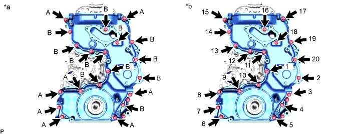
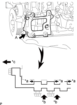
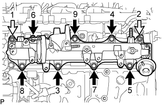
Temporarily install the timing chain case assembly with the 15 bolts.
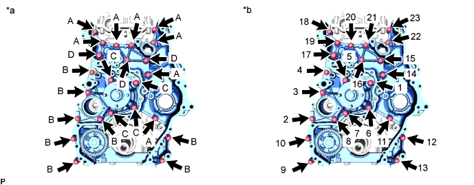
Text in Illustration *a Type of bolt *b Tightening Bolt Length Item Length Thread Diameter Bolt A 30 mm (1.18 in.) 8.0 mm (0.315 in.) Bolt B 45 mm (1.77 in.) 8.0 mm (0.315 in.) Bolt C 65 mm (2.56 in.) 8.0 mm (0.315 in.) Bolt D 30 mm (1.18 in.) 10 mm (0.394 in.) -
Temporarily install a new gasket and the engine water pump assembly with the 8 bolts.
-
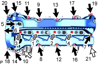
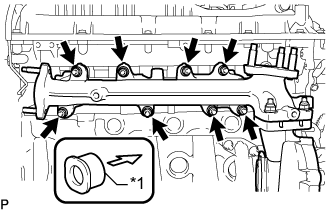
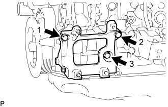
Tighten the 23 bolts in the order shown in the illustration.
- Torque:
- for bolt A, B and C
- 25 N*m { 255 kgf*cm, 18 ft.*lbf }
- for bolt D
- 43 N*m { 438 kgf*cm, 32 ft.*lbf }
Note
Check the torque of bolt 1 after tightening bolt 23.
-
-
INSTALL FAN PULLEY
-
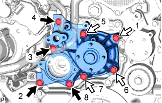
Temporarily install a new gasket and the water pump assembly with the 8 bolts.
Standard Length Item Specified Condition Bolt A 45 mm (1.77 in.) Bolt B 65 mm (2.56 in.) Text in Illustration 
Bolt A 
Bolt B -
Tighten the 8 bolts in the order shown in the illustration.
- Torque:
- 25 N*m { 255 kgf*cm, 18 ft.*lbf }
-
-
INSTALL INJECTION PUMP INSULATOR
-
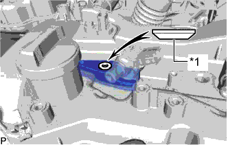
Install the injection pump insulator to the cylinder block sub-assembly.
-
-
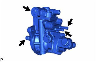
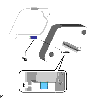
INSTALL SUPPLY PUMP ASSEMBLY
Note
Do not hold the supply pump assembly by the parts indicated by the arrows in the illustration.
-
Install a new O-ring to the supply pump assembly.
-
Install the supply pump assembly to the timing chain case assembly with the 3 nuts.
- Torque:
- 21 N*m { 214 kgf*cm, 15 ft.*lbf }
-
Install the No. 1 fuel pump bracket to the cylinder block sub-assembly and supply pump assembly with the 2 bolts.
- Torque:
- 21 N*m { 214 kgf*cm, 15 ft.*lbf }
-
-
INSTALL NO. 1 CHAIN TENSIONER SLIPPER
-
Install the No. 1 chain tensioner slipper to the straight pin.
-
-
TEMPORARILY INSTALL NO. 1 CHAIN VIBRATION DAMPER
-
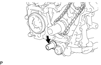
Temporarily install the No. 1 chain vibration damper to the cylinder block sub-assembly with the bolt.
-
-
INSTALL CRANKSHAFT TIMING GEAR OR SPROCKET, INJECTION PUMP DRIVE GEAR WITH NO. 1 CHAIN SUB-ASSEMBLY
-
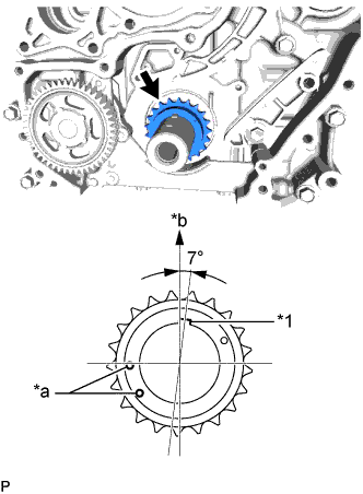
Text in Illustration *1 Crankshaft Pulley Set Key *a Timing Mark *b Upper Side Install the crankshaft timing sprocket to the crankshaft.
-
Align the crankshaft pulley set key as shown in the illustration.
-
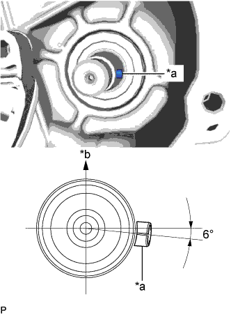
Text in Illustration *a Supply Pump Shaft Key *b Upper Side Align the supply pump shaft key as shown in the illustration.
-
Remove the crankshaft timing sprocket from the crankshaft.
-
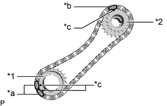
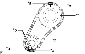
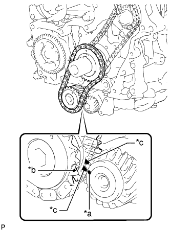
Text in Illustration *1 Crankshaft Timing Sprocket *2 Injection Pump Drive Gear *a Mark Plate (Pink) *b Mark Plate (Yellow) *c Timing Mark Align the 2 mark plates (pink) of the No. 1 chain sub-assembly with the 2 timing marks of the crankshaft timing sprocket and install the No. 1 chain sub-assembly to the crankshaft timing sprocket as shown in the illustration.
-
Align the mark plate (yellow) of the No. 1 chain sub-assembly with the timing mark of the injection pump drive gear and install the No. 1 chain sub-assembly to the injection pump drive gear as shown in the illustration.
-
Install the crankshaft timing sprocket, injection pump drive gear and No. 1 chain sub-assembly to the crankshaft and supply pump shaft together.
-
-
TIGHTEN NO. 1 CHAIN VIBRATION DAMPER
-
Tighten the No. 1 chain vibration damper to the cylinder block sub-assembly with the bolt.
- Torque:
- 21 N*m { 214 kgf*cm, 15 ft.*lbf }
-
-
INSTALL NO. 1 CHAIN TENSIONER ASSEMBLY
Note
-
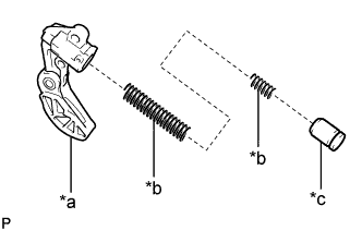
When the pin is removed from the No. 1 chain tensioner assembly, the plunger and spring may come off of the No. 1 chain tensioner assembly body, but this is not a malfunction.
-
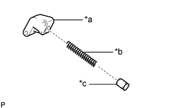
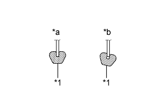
Before installing the plunger and spring to the No. 1 chain tensioner assembly body, check that they are free of foreign matter and not damaged.
Text in Illustration *a No. 1 Chain Tensioner Assembly Body *b Spring *c Plunger
-
Text in Illustration *a Claw (Lower Side) *b Groove Install a new gasket and No. 1 chain tensioner assembly to the cylinder block sub-assembly with the 2 bolts.
- Torque:
- 10 N*m { 102 kgf*cm, 7 ft.*lbf }
Tech Tips
Align the claw (lower side) of the gasket with the groove of the No. 1 chain tensioner assembly body to install the No. 1 chain tensioner assembly as shown in the illustration.
-
-
INSTALL SUPPLY PUMP SHAFT NUT
-
Temporarily install the crankshaft pulley and crankshaft pulley set bolt to the crankshaft.
-
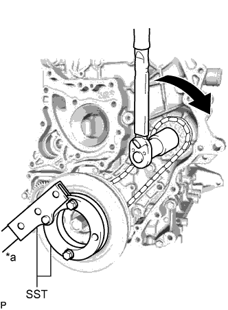
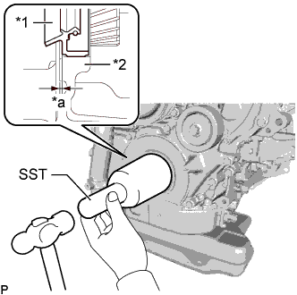
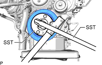
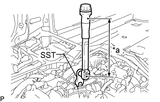
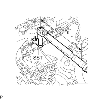
Text in Illustration *a Hold Turn Using SST, hold the crankshaft pulley and install the supply pump shaft nut to the supply pump shaft.
- SST
- 09213-58014 ( 91551-80840 )
- 09330-00021
- Torque:
- 137 N*m { 1397 kgf*cm, 101 ft.*lbf }
Note
If the supply pump shaft nut is tightened with torque higher than the specified torque, the No. 1 chain sub-assembly may break.
-
Remove the crankshaft pulley set bolt and crankshaft pulley from the crankshaft.
-
Text in Illustration *1 Crankshaft Timing Sprocket *2 Injection Pump Drive Gear *a Mark Plate (Pink) *b Mark Plate (Yellow) *c Timing Mark Make sure that the timing marks of the crankshaft timing sprocket and injection pump drive gear are aligned with the mark plates of the No. 1 chain sub-assembly as shown in the illustration.
-
Remove the pin from the No. 1 chain tensioner assembly.
-
-
INSTALL CAMSHAFT TIMING SPROCKET
-
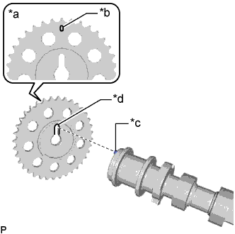
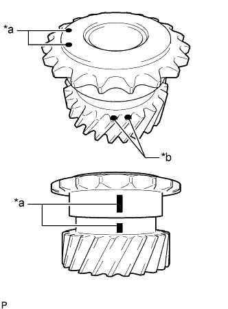
Text in Illustration *a Engine Front Side *b Timing Mark *c Knock Pin *d Cutout Temporarily install the 2 camshaft timing sprockets to the camshaft and No. 2 camshaft with the 2 camshaft timing sprocket bolts.
Note
Make sure that the timing mark of the camshaft timing sprocket faces the front side of the engine.
Tech Tips
Align the knock pins of the camshaft and No. 2 camshaft with the cutout of the camshaft timing sprocket to install the camshaft timing sprocket.
-
for Intake Side:
-
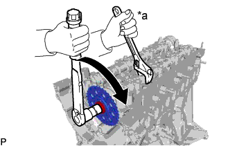
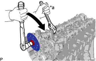
Text in Illustration *a Hold Turn Using a wrench to hold the hexagonal portion of the camshaft, install the camshaft timing sprocket bolt to the camshaft.
- Torque:
- 81 N*m { 826 kgf*cm, 60 ft.*lbf }
Note
Be careful not to damage the camshaft or cylinder head sub-assembly with the wrench.
-
-
for Exhaust Side:
-
Text in Illustration *a Hold Turn Using a wrench to hold the hexagonal portion of the No. 2 camshaft, install the camshaft timing sprocket bolt to the No. 2 camshaft.
- Torque:
- 81 N*m { 826 kgf*cm, 60 ft.*lbf }
Note
Be careful not to damage the No. 2 camshaft or cylinder head sub-assembly with the wrench.
-
-
-
INSTALL NO. 2 CHAIN VIBRATION DAMPER
-
Install the No. 2 chain vibration damper to the timing chain case assembly with the 2 bolts.
- Torque:
- 21 N*m { 214 kgf*cm, 15 ft.*lbf }
-
-
INSTALL NO. 2 CHAIN SUB-ASSEMBLY
-
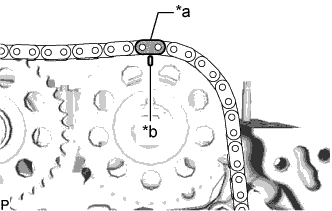
Text in Illustration *a Mark Plate (Orange) *b Timing Mark Align the mark plate (orange) of the No. 2 chain sub-assembly with the timing mark of the camshaft timing sprocket (intake side) and install the No. 2 chain sub-assembly to the camshaft timing sprocket (intake side) as shown in the illustration.
-
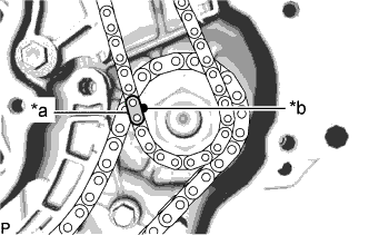
Text in Illustration *a Mark Plate (Yellow) *b Timing Mark Align the mark plate (yellow) of the No. 2 chain sub-assembly with the timing mark of the injection pump drive gear and install the No. 2 chain sub-assembly to the injection pump drive gear as shown in the illustration.
-
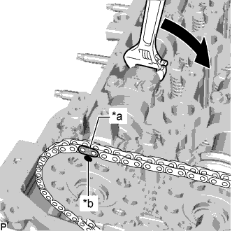
Text in Illustration *a Mark Plate (Orange) *b Timing Mark Turn Using a wrench, turn the hexagonal portion of the No. 2 camshaft clockwise and align the mark plate (orange) of the No. 2 chain sub-assembly with the timing mark of the camshaft timing sprocket (exhaust side) to install the No. 2 chain sub-assembly to the camshaft timing sprocket (exhaust side).
-
-
INSTALL NO. 2 CHAIN TENSIONER SLIPPER
-
Install the No. 2 chain tensioner slipper to the timing chain case assembly with the bolt.
- Torque:
- 21 N*m { 214 kgf*cm, 15 ft.*lbf }
-
-
INSTALL NO. 2 CHAIN TENSIONER ASSEMBLY
-
Install the No. 2 chain tensioner assembly to the timing chain case assembly with the 2 bolts.
- Torque:
- 10 N*m { 102 kgf*cm, 7 ft.*lbf }
-
Remove the pin from the No. 2 chain tensioner assembly.
-
-
INSTALL TIMING CHAIN GUIDE
-
Install the timing chain guide to the cylinder head sub-assembly with the bolt.
- Torque:
- 10 N*m { 102 kgf*cm, 7 ft.*lbf }
-
-
CHECK NO. 1 CYLINDER TO TDC/COMPRESSION
-
Make sure that the timing marks of the camshaft timing sprocket (exhaust side), camshaft timing sprocket (intake side), injection pump drive gear and crankshaft timing sprocket are at the positions shown in the illustration.
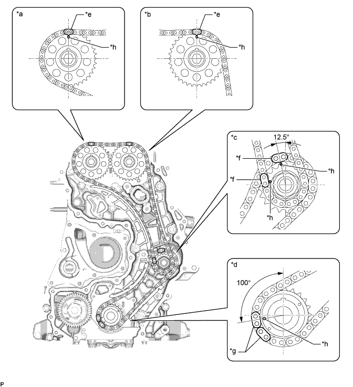
Text in Illustration *a Camshaft Timing Sprocket (Exhaust Side) *b Camshaft Timing Sprocket (Intake Side) *c Injection Pump Drive Gear *d Crankshaft Timing Sprocket *e Mark Plate (Orange) *f Mark Plate (Yellow) *g Mark Plate (Pink) *h Timing Mark
-
-
INSTALL BALANCE SHAFT TIMING SPROCKET, BALANCE SHAFT TIMING GEAR AND NO. 3 CHAIN SUB-ASSEMBLY
Tech Tips
Before installing the balance shaft gear sub-assembly, make sure to confirm the positions of the timing marks and paint marks (pink).
-
Text in Illustration *a Timing Mark *b Paint Mark (Pink) Align the mark plate (yellow) of the No. 3 chain sub-assembly with the timing mark of the balance shaft timing sprocket and install the No. 3 chain sub-assembly to the balance shaft timing sprocket as shown in the illustration.
Note
Make sure that the timing plate of the No. 3 chain sub-assembly faces the front side of the engine.
-
Align the 2 mark plates (yellow) of the No. 3 chain sub-assembly with the 2 timing marks of the balance shaft timing gear sub-assembly and install the No. 3 chain sub-assembly to the balance shaft timing gear sub-assembly as shown in the illustration.
-
Text in Illustration *1 Balance Shaft Timing Sprocket *2 Balance Shaft Gear Sub-assembly *a Mark Plate (Yellow) *b Timing Mark Apply engine oil to the position shown in the illustration.
-
Text in Illustration *a Timing Mark (Engine Balancer Assembly Side) *b Timing Mark (Balance Shaft Gear Sub-assembly Side) *c Paint Mark (Pink)
(Balance Shaft Gear Sub-assembly Side)
Align the timing mark of the engine balancer assembly with the 2 paint marks (pink) and timing mark of the balance shaft gear sub-assembly, and then install the balance shaft timing sprocket, balance shaft gear sub-assembly with No. 3 chain sub-assembly to the crankshaft and engine balancer assembly as shown in the illustration.
-
Text in Illustration *1 Balance Shaft Timing Sprocket *2 Balance Shaft Gear Sub-assembly *a Mark Plate (Yellow) *b Timing Mark Make sure that the timing marks of the balance shaft timing sprocket and balance shaft gear sub-assembly are aligned with the mark plates of the No. 3 chain sub-assembly as shown in the illustration.
-
-
INSTALL NO. 1 BALANCE SHAFT THRUST PLATE
-
Apply engine oil to the front and rear surfaces of the No. 1 balance shaft thrust plate.
-
Install the No. 1 balance shaft thrust plate to the crankshaft with the bolt.
- Torque:
- 21 N*m { 214 kgf*cm, 15 ft.*lbf }
-
-
INSTALL NO. 3 CHAIN TENSIONER ASSEMBLY
Note
-
When the pin is removed from the No. 3 chain tensioner assembly, the plunger and 2 springs may come off of the No. 3 chain tensioner assembly body, but this is not a malfunction.
-
Before installing the plunger and 2 springs to the No. 3 chain tensioner assembly body, check that they are free of foreign matter and not damaged.
Text in Illustration *a No. 3 Chain Tensioner Assembly Body *b Spring *c Plunger
-
Install the No. 3 chain tensioner assembly to the engine balancer assembly with the 2 bolts.
- Torque:
- 10 N*m { 102 kgf*cm, 7 ft.*lbf }
-
Remove the pin from the No. 3 chain tensioner assembly.
-
-
INSTALL OIL PUMP DRIVE GEAR
-
Install the oil pump drive gear to the crankshaft.
-
-
INSTALL TIMING CHAIN COVER PLATE
-
Install the timing chain cover plate and new gasket with the 3 bolts.
- Torque:
- 10 N*m { 102 kgf*cm, 7 ft.*lbf }
-
-
INSTALL TIMING CHAIN COVER SUB-ASSEMBLY
-
Install the timing chain case gasket to the timing chain case assembly.
-
Clean and degrease the contact surfaces of the timing chain cover sub-assembly and timing chain case assembly.
-
Apply a coating of seal packing to the timing chain cover sub-assembly at the points shown in the illustration.
Text in Illustration *a 2.0 to 3.0 mm (0.0787 to 0.118 in.) *b 2.5 to 3.5 mm (0.0984 to 0.138 in.) Seal packing Toyota Genuine Seal Packing Black, Three Bond 1207B or equivalent. Standard seal packing diameter 2.5 to 3.5 mm (0.0984 to 0.138 in.) Note
-
Using non-residue solvent, clean and remove any oil from the installation surface.
-
Install the part within 3 minutes and tighten the bolts within 10 minutes after applying seal packing.
-
Do not add engine oil for at least 2 hours after installation.
-
Do not start the engine within 2 hours after installation.
-
-
Temporarily install the timing chain cover sub-assembly with the 20 bolts.
Text in Illustration *a Type of bolt *b Tightening Bolt Length Item Length Thread Diameter Bolt A 40 mm (1.57 in.) 8.0 mm (0.315 in.) Bolt B 25 mm (0.984 in.) 8.0 mm (0.315 in.) -
Tighten the 20 bolts in the order shown in the illustration.
- Torque:
- 21 N*m { 214 kgf*cm, 15 ft.*lbf }
Note
Check the torque of bolt 1 after tightening bolt 20.
-
-
INSTALL FRONT CRANKSHAFT OIL SEAL
-
Apply MP grease to the lip of a new crankshaft oil seal.
Note
-
Keep the lip free of foreign objects.
-
Do not allow MP grease to contact the dust seal.
-
-
Text in Illustration *1 Front Crankshaft Oil Seal *2 Timing Chain Cover Assembly *a 0 to 1.5 mm (0 to 0.0591 in.) Using SST and a hammer, tap in the front crankshaft oil seal.
- SST
- 09214-76011
Note
-
The acceptable depth from the top of the timing chain cover assembly is 0 to 1.5 mm (0 to 0.0591 in.)
-
Keep the lip free from foreign matter.
-
Do not tap the front crankshaft oil seal at an angle.
-
Make sure that the front crankshaft oil seal is properly installed.
-
-
INSTALL OIL PAN SUB-ASSEMBLY
-
Clean and degrease the contact surfaces of the oil pan sub-assembly and cylinder block sub-assembly.
-
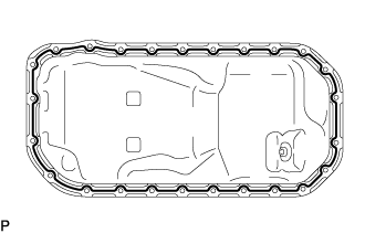
Apply seal packing in a continuous line as shown in the illustration.
Text in Illustration 
Seal Packing Seal packing Toyota Genuine Seal Packing Black, Three Bond 1207B or equivalent Standard seal diameter 3.5 to 4.5 mm (0.138 to 0.177 in.) Note
-
Remove any oil from the contact surface.
-
Install the oil pan sub-assembly within 3 minutes and tighten the bolts and nuts within 10 minutes after applying seal packing.
-
Do not add engine oil within 2 hours after installation.
-
Do not start the engine for at least 2 hours after installation.
-
-
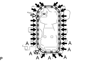
Install the oil pan sub-assembly to the cylinder block sub-assembly with the 23 bolts and 2 nuts.
- Torque:
- 10 N*m { 102 kgf*cm, 7 ft.*lbf }
Note
Check the torque of all nuts and bolts labeled A again.
-
-
INSTALL ENGINE OIL LEVEL SENSOR
-
Install the engine oil level sensor to the oil pan sub-assembly with the 4 bolts.
- Torque:
- 12 N*m { 122 kgf*cm, 9 ft.*lbf }
-
Connect the engine oil level sensor connector.
-
-
INSTALL CYLINDER HEAD COVER SUB-ASSEMBLY
-
Apply a light coat of engine oil to the O-ring of the camshaft position sensor.
-
Install a new cylinder head cover gasket, No. 2 cylinder head cover gasket and 2 camshaft bearing cap oil hole gaskets to the cylinder head cover sub-assembly.
-
Clean and degrease the contact surfaces of the cylinder head cover sub-assembly and cylinder head sub-assembly.
-
Apply seal packing as shown in the illustration.
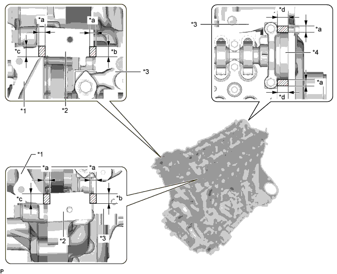
Text in Illustration *1 Timing Chain Cover Sub-assembly *2 Timing Chain Case Assembly *3 Cylinder Head Sub-assembly *4 No. 3 Camshaft Bearing Cap *a Seal Diameter: 3.0 to 6.0 mm (0.118 to 0.236 in.) *b Application Width: 7.0 mm (0.276 in.) *c Application Width: 9.0 mm (0.354 in.) *d Application Width: 11.0 mm (0.433 in.) Seal packing Toyota Genuine Seal Packing Black, Three Bond 1207B or equivalent Standard seal diameter 3.0 to 6.0 mm (0.118 to 0.236 in.) Note
-
Remove any oil from the contact surface.
-
Install the cylinder head cover sub-assembly within 3 minutes and tighten the bolts within 10 minutes after applying seal packing.
-
Do not add engine oil for at least 2 hours after installation.
-
Do not start the engine within 2 hours after installation.
-
-
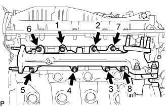
Tighten the 14 bolts, 4 nozzle holder clamp seats, 2 nuts and camshaft position sensor in the order shown in the illustration.
- Torque:
- 10 N*m { 107 kgf*cm, 7 ft.*lbf }
Note
-
When reusing the camshaft position sensor, check the O-rings.
-
Make sure that the O-ring is not cracked or jammed when installing it on the cylinder head cover sub-assembly.
-
Replace with a new part if it is dropped or if it receives a strong impact.
-
Check the torque of bolts 1 to 4 again.
Text in Illustration Bolt Nut 
Nozzle Holder Clamp Seat
-
-
INSTALL NOZZLE HOLDER GASKET
-
Install 4 new nozzle holder gaskets to the cylinder head cover sub-assembly.
-
-
TEMPORARILY INSTALL INJECTOR ASSEMBLY
Tech Tips
Before installing the injector assembly, check for carbon, foreign matter, etc. on the seal surfaces of the cylinder head sub-assembly and injector assembly. If there is foreign matter, remove it before installing the injector assembly.
-
Install 4 new injection nozzle seats to the cylinder head sub-assembly.
-
Apply a light coat of engine oil to the O-ring on each injector assembly.
-
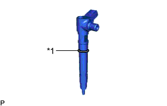
Text in Illustration *1 O-Ring Install a new O-ring to each injector assembly.
-
Install the 4 injector assemblies to the cylinder head sub-assembly.
Note
Fit the injector assembly to the injection nozzle seats.
-
Text in Illustration *1 Washer Install the nozzle holder clamps and washers as shown in the illustration.
Note
Pay attention to the mounting orientation (beveled edge) of the washer.
-
Temporarily install the nozzle holder clamp bolts.
Note
When temporarily installing the nozzle holder clamp bolt to the No. 1 nozzle holder clamp, make sure that the bolt and clamp are not at an angle.
Tech Tips
Apply a light coat of engine oil to the threads of the nozzle holder clamp bolts.
-
-
INSTALL GENERATOR BRACKET SUB-ASSEMBLY
-
Install the generator bracket sub-assembly to the cylinder head sub-assembly and timing chain case assembly with the 4 bolts.
- Torque:
- 21 N*m { 214 kgf*cm, 15 ft.*lbf }
-
-
INSTALL NO. 1 ENGINE HANGER
-
Install the No. 1 engine hanger to the cylinder head sub-assembly with the 2 bolts.
- Torque:
- 26 N*m { 265 kgf*cm, 19 ft.*lbf }
-
-
INSTALL CRANKSHAFT PULLEY
-
Align the keyway of the crankshaft pulley with the key located on the crankshaft, and then slide the crankshaft pulley into place to install it.
-
Using SST, install a new pulley bolt.
- SST
- 09213-58014 ( 91551-80840 )
- 09330-00021
- Torque:
- 365 N*m { 3722 kgf*cm, 269 ft.*lbf }
-
-
INSTALL CRANKSHAFT PULLEY COVER
-
Install the crankshaft pulley cover to the crankshaft pulley with the 4 bolts.
- Torque:
- 21 N*m { 214 kgf*cm, 15 ft.*lbf }
-
-
INSTALL V-RIBBED BELT TENSIONER ASSEMBLY
-
Install the V-ribbed belt tensioner assembly to the timing chain cover sub-assembly with the 3 bolts.
- Torque:
- 21 N*m { 214 kgf*cm, 15 ft.*lbf }
-
-
INSTALL NO. 1 IDLER PULLEY SUB-ASSEMBLY
-
Install the No. 1 idler pulley sub-assembly to the generator bracket sub-assembly with the bolt.
- Torque:
- 43 N*m { 438 kgf*cm, 32 ft.*lbf }
-
-
INSTALL THERMOSTAT
-
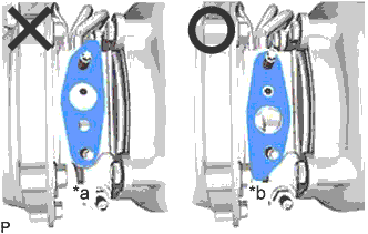
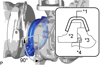
Text in Illustration *1 Gasket *a CORRECT *b INCORRECT Install a new gasket to the thermostat as shown in the illustration.
Note
When installing the gasket to the thermostat, be careful not to deform the gasket. Make sure that the groove of the gasket is properly installed to the thermostat as shown in the illustration.
-
Text in Illustration *a Upward *b 30° *c Jiggle Valve Insert the thermostat into the engine water pump assembly with the jiggle valve facing straight upward.
Tech Tips
The jiggle valve may be set to within 30° on either side of the prescribed position.
-
-
INSTALL WATER INLET
-
Install the water inlet to the engine water pump assembly with the 2 bolts.
- Torque:
- 13 N*m { 133 kgf*cm, 10 ft.*lbf }
-
-
INSTALL WATER OUTLET SUB-ASSEMBLY
-
Install a new gasket and the water outlet sub-assembly to the timing chain cover sub-assembly with the 4 bolts and 2 nuts.
- Torque:
- 10 N*m { 102 kgf*cm, 7 ft.*lbf }
-
-
INSTALL NO. 2 WATER BY-PASS PIPE SUB-ASSEMBLY
-
Install the No. 2 water by-pass pipe sub-assembly to the engine water pump assembly and water inlet with the 2 bolts.
- Torque:
- 10 N*m { 102 kgf*cm, 7 ft.*lbf }
-
Connect the No. 3 water by-pass hose to the water outlet sub-assembly, and slide the clamp to secure the hose.
-
-
TEMPORARILY INSTALL TURBO OIL INLET PIPE SUB-ASSEMBLY
-
Text in Illustration *a NG *b OK Install a new gasket as shown in the illustration.
Note
Do not install the gasket upside down.
-
Temporarily install the turbo oil inlet pipe sub-assembly with the 2 nuts.
-
-
TEMPORARILY INSTALL EXHAUST MANIFOLD WITH TURBOCHARGER SUB-ASSEMBLY
-
Install 2 new gaskets to the exhaust manifold and turbocharger sub-assembly.
-
Temporarily install the exhaust manifold to turbocharger sub-assembly with 3 new nuts.
-
Text in Illustration *1 Collar Engine Side Temporarily install the exhaust manifold with turbocharger sub-assembly, 8 collars and 8 plate washers to the cylinder head sub-assembly with 8 new nuts.
Note
Make sure that the side of the collar with the smaller diameter faces the exhaust manifold.
-
Install a new gasket on the union bolt side to turbo oil inlet pipe sub-assembly.
-
Temporarily install the union bolt.
-
-
INSTALL TURBO OIL OUTLET PIPE
-
Install a new gasket to the turbo oil outlet pipe.
Note
The claws of the gasket must face the turbo oil outlet pipe.
-
Install the turbo oil outlet pipe with the 2 bolts.
- Torque:
- 12 N*m { 122 kgf*cm, 9 ft.*lbf }
-
Connect the turbo oil outlet hose to the turbo oil outlet pipe, turbo oil inlet pipe and slide the 2 hose clips to secure the hoses.
-
-
TEMPORARILY INSTALL TURBOCHARGER STAY
-
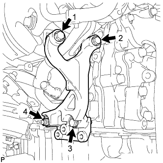
Temporarily install the turbocharger stay to the turbocharger sub-assembly with the 3 bolts and nut.
-
-
TIGHTEN EXHAUST MANIFOLD WITH TURBOCHARGER SUB-ASSEMBLY
-
Tighten the exhaust manifold with turbocharger sub-assembly to the cylinder head sub-assembly with the 8 nuts.
- Torque:
- 40 N*m { 408 kgf*cm, 30 ft.*lbf }
Tech Tips
Tighten the nuts in the order shown in the illustration.
-
Tighten the turbocharger sub-assembly to the exhaust manifold with the 3 nuts.
- Torque:
- 73 N*m { 744 kgf*cm, 54 ft.*lbf }
-
Tighten the 2 nuts and union bolt of the turbo oil inlet pipe sub-assembly.
- Torque:
- for nut
- 13 N*m { 133 kgf*cm, 10 ft.*lbf }
- for union bolt
- 36 N*m { 367 kgf*cm, 27 ft.*lbf }
Note
If the connecting part of the union bolt gasket is cracked, remove the connecting part.
-
-
TIGHTEN TURBOCHARGER STAY
-
Tighten the 3 bolts and nut of the turbocharger stay in the order shown in the illustration.
- Torque:
- 24 N*m { 245 kgf*cm, 18 ft.*lbf }
-
-
CONNECT NO. 1 AND NO. 2 TURBO WATER HOSE
Note
The turbocharger sub-assembly may be damaged if the No. 1 turbo water hose and No. 2 turbo water hose are connected to the wrong locations.
-
Connect the No. 2 turbo water hose to the water outlet sub-assembly, and slide the 2 hose clips to secure the hoses.
-
Connect the No. 1 turbo water hose to the engine water pump assembly, and slide the 2 hose clips to secure the hoses.
-
-
INSTALL NO. 1 WATER BY-PASS PIPE
-
Install a new gasket and the No. 1 water by-pass pipe to the timing chain cover sub-assembly with the 2 bolts.
- Torque:
- 10 N*m { 102 kgf*cm, 7 ft.*lbf }
Tech Tips
Make sure that the claw of the gasket faces the No. 1 water by-pass pipe.
-
-
INSTALL FRONT ENGINE MOUNTING INSULATOR
-
INSTALL FRONT ENGINE MOUNTING INSULATOR RH
-
INSTALL EXHAUST MANIFOLD CONVERTER SUB-ASSEMBLY
-
Set a new gasket and the exhaust manifold converter sub-assembly to the turbocharger sub-assembly.
-
Temporarily install the exhaust pipe support stay to the cylinder block sub-assembly and exhaust manifold converter sub-assembly with the 3 bolts.
-
Text in Illustration *1 Exhaust Pipe Clamp *2 Exhaust Manifold Converter *3 Turbocharger Sub-assembly *4 Gasket Install a new exhaust pipe clamp to the exhaust manifold converter sub-assembly with a new nut.
- Torque:
- 18 N*m { 184 kgf*cm, 13 ft.*lbf }
-
Tighten the 3 bolts and install the exhaust pipe support stay to the cylinder block sub-assembly and exhaust manifold converter sub-assembly.
- Torque:
- 38 N*m { 387 kgf*cm, 28 ft.*lbf }
-
-
INSTALL NO. 2 EXHAUST PIPE SUPPORT STAY
-
Install the No. 2 exhaust pipe support stay to the cylinder block sub-assembly and exhaust manifold converter sub-assembly with the bolt and 2 new nuts.
- Torque:
- 38 N*m { 387 kgf*cm, 28 ft.*lbf }
-
-
INSTALL NO. 1 TURBO INSULATOR
-
Install the No. 1 turbo insulator to the exhaust manifold and turbocharger sub-assembly with the 3 bolts.
- Torque:
- 12 N*m { 122 kgf*cm, 9 ft.*lbf }
-
-
INSTALL NO. 1 EXHAUST MANIFOLD HEAT INSULATOR
-
Install the No. 1 exhaust manifold heat insulator to the exhaust manifold with the 3 bolts.
- Torque:
- 12 N*m { 122 kgf*cm, 9 ft.*lbf }
-
-
INSTALL AIR FUEL RATIO SENSOR
Tech Tips
Perform "Inspection After Repairs" after replacing the air fuel ratio sensor Click here.
-
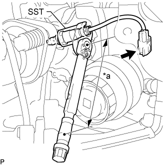
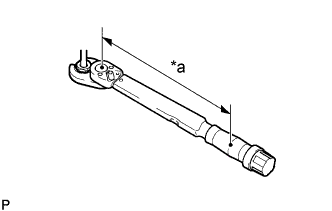
Text in Illustration *a Torque Wrench Fulcrum Length Using SST, install the air fuel ratio sensor to the front exhaust pipe.
- SST
- 09224-00012
- Torque:
- Specified tightening torque
- 44 N*m { 449 kgf*cm, 32 ft.*lbf }
Tech Tips
-
Calculate the torque wrench reading when changing the fulcrum length of the torque wrench Click here.
-
When using SST (fulcrum length of 30 mm (1.18 in.)) + torque wrench (fulcrum length of 180 mm (7.09 in.)): 38 N*m (384 kgf*cm, 28 ft.*lbf)
-
Connect the connector.
-
-
INSTALL NO. 2 EXHAUST MANIFOLD HEAT INSULATOR
-
Install a new gasket and the No. 2 exhaust manifold heat insulator to the No. 1 injector holder with the 3 nuts.
- Torque:
- 10 N*m { 102 kgf*cm, 7 ft.*lbf }
-
-
INSTALL NO. 1 INJECTOR HOLDER
-
Install the injector holder to the No. 1 injector holder with the 2 bolts.
- Torque:
- 10 N*m { 102 kgf*cm, 7 ft.*lbf }
-
-
CONNECT NO. 4 WATER BY-PASS HOSE
-
Connect the No. 4 water by-pass hose to the No. 1 injector holder, and slide the clamp to secure the hose.
-
-
INSTALL NO. 5 WATER BY-PASS HOSE
-
Attach the clamp and install the No. 5 water by-pass hose to the hose clamp.
-
Connect the No. 5 water by-pass hose to the No. 1 injector holder and water outlet sub-assembly, and slide the 2 clamps to secure the hose.
-
-
INSTALL PCV HOSE
-
Attach the clamp, install the PCV hose and slide the 2 hose clips to secure the hoses.
-
Slide the 2 hose clips to secure the hoses.
-
-
INSTALL NO. 1 COMPRESSOR MOUNTING BRACKET
Note
Install the No. 1 compressor mounting bracket exactly as described in the procedures below to properly secure and prevent damage to the fan and generator V belt.
-
Temporarily install the No. 1 compressor mounting bracket to the cylinder block sub-assembly with the 2 bolts.
Tech Tips
Temporarily install the No. 1 compressor mounting bracket with the 2 bolts so that the No. 1 compressor mounting bracket can be moved by hand.
-
Text in Illustration *a No Clearance *b Push *c Front Push the No. 1 compressor mounting bracket toward the cylinder block sub-assembly as shown in the illustration and tighten bolt A.
- Torque:
- 39 N*m { 398 kgf*cm, 29 ft.*lbf }
Tech Tips
Make sure there is no clearance between the cylinder block sub-assembly and No. 1 compressor mounting bracket as shown in the illustration.
-
Uniformly tighten the 3 bolts in the order shown in the illustration.
- Torque:
- 39 N*m { 398 kgf*cm, 29 ft.*lbf }
-
-
INSTALL COOLER COMPRESSOR ASSEMBLY
-
INSTALL BRACKET
-
Install the bracket to the cylinder head sub-assembly with the 2 bolts.
- Torque:
- 10 N*m { 102 kgf*cm, 7 ft.*lbf }
-
-
TEMPORARILY INSTALL NO. 1 AND NO. 2 INJECTION PIPE SUB-ASSEMBLY
-
Temporarily install the 2 No. 2 injection pipe sub-assemblies with the 4 union nuts.
-
Temporarily install the 2 No. 1 injection pipe sub-assemblies with the 4 union nuts.
-
-
TIGHTEN INJECTOR ASSEMBLY
-
Tighten the 4 nozzle holder clamp bolts.
- Torque:
- 21 N*m { 214 kgf*cm, 15 ft.*lbf }
-
-
TIGHTEN NO. 1 AND NO. 2 INJECTION PIPE SUB-ASSEMBLY
-
Text in Illustration *a Torque Wrench Fulcrum Length Using SST, tighten the 8 union nuts of the No. 1 and No. 2 injection pipe sub-assemblies.
- Torque:
- Specified tightening torque
- 40 N*m { 408 kgf*cm, 30 ft.*lbf }
Tech Tips
-
Calculate the torque wrench reading when changing the fulcrum length of the torque wrench.
-
When using SST (fulcrum length of 50 mm (1.97 in.)) + torque wrench (fulcrum length of 180 mm (7.09 in.)): 31 N*m (316 kgf*cm, 23 ft.*lbf)
-
-
INSTALL WIRING HARNESS CLAMP BRACKET
-
for Upper Side:
Install the wiring harness clamp bracket to the cylinder head cover sub-assembly with the bolt.
- Torque:
- 10 N*m { 102 kgf*cm, 7 ft.*lbf }
-
for Rear Side:
Install the wiring harness clamp bracket to the cylinder head cover sub-assembly with the bolt.
- Torque:
- 13 N*m { 127 kgf*cm, 9 ft.*lbf }
-
-
INSTALL NOZZLE LEAKAGE PIPE ASSEMBLY
-
Temporarily install the nozzle leakage pipe assembly and 4 new gaskets with the 4 union bolts and bolt.
-
Tighten the 4 union bolts and bolt in the order shown in the illustration.
- Torque:
- 10 N*m { 102 kgf*cm, 7 ft.*lbf }
-
Connect the No. 5 fuel hose to the nozzle leakage pipe assembly.
-
-
INSTALL NO. 1 FUEL PIPE
-
Connect the No. 1 fuel pipe to the No. 4 fuel pipe.
-
Install a new gasket and the No. 1 fuel pipe to the cylinder head cover sub-assembly and No. 1 injector holder with the union bolt and bolt.
- Torque:
- for bolt
- 10 N*m { 102 kgf*cm, 7 ft.*lbf }
- for union bolt
- 36 N*m { 367 kgf*cm, 27 ft.*lbf }
-
-
INSTALL WIRING HARNESS CLAMP BRACKET
-
Install the wiring harness clamp bracket the cylinder head cover sub-assembly with the bolt.
- Torque:
- 10 N*m { 102 kgf*cm, 7 ft.*lbf }
-
Connect the pressure discharge valve connector to the common rail assembly.
-
-
INSTALL INTAKE MANIFOLD
-
Install a new gasket to the cylinder head sub-assembly.
Tech Tips
Install the gasket with the protrusion facing the rear side of the vehicle as shown in the illustration.
Text in Illustration *a Protrusion Rear side -
Temporarily install the intake manifold with the 7 bolts and 2 nuts.
-
Tighten the 7 bolts and 2 nuts in the order shown in the illustration.
- Torque:
- 23 N*m { 235 kgf*cm, 17 ft.*lbf }
Text in Illustration Bolt Nut -
Connect the wire harness bracket with the bolt.
- Torque:
- 13 N*m { 130 kgf*cm, 9 ft.*lbf }
-
-
INSTALL NO. 2 NOZZLE LEAKAGE PIPE ASSEMBLY
-
Install the No. 2 nozzle leakage pipe assembly with the 2 bolts.
- Torque:
- 10 N*m { 102 kgf*cm, 7 ft.*lbf }
-
Connect the No. 6 fuel hose to the No. 3 nozzle leakage pipe assembly, and slide the clamp to secure the hose.
-
Install the No. 4 fuel hose to the No. 2 nozzle leakage pipe assembly, common rail assembly and slide the 2 clamps to secure the hoses.
-
Install the No. 5 fuel hose to the No. 2 nozzle leakage pipe assembly, No. 1 nozzle leakage pipe assembly and slide the 2clamps to secure the hoses.
-
-
INSTALL FUEL INLET PIPE SUB-ASSEMBLY
Note
When replacing the fuel supply pump assembly, it is necessary to replace the fuel inlet pipe sub-assembly, No. 1 injection pipe clamp and No. 2 injection pipe clamp with a new one. Keep the fuel inlet pipe sub-assembly free of foreign matter.
-
Temporarily install the fuel inlet pipe sub-assembly.
-
Install a new No. 1 injection pipe clamp and No. 2 injection pipe clamp with the 2 bolts.
- Torque:
- 10 N*m { 102 kgf*cm, 7 ft.*lbf }
-
Text in Illustration *a Torque Wrench Fulcrum Length Using SST, tighten the fuel inlet pipe sub-assembly union nut on the common rail side sub-assembly.
- SST
- 09245-11010
- Torque:
- Specified tightening torque
- 40 N*m { 408 kgf*cm, 30 ft.*lbf }
Tech Tips
-
Calculate the torque wrench reading when changing the fulcrum length of the torque wrench.
-
When using a union nut wrench (fulcrum length of 50 mm (1.97 in.)) + torque wrench (fulcrum length of 180 mm (7.09 in.)): 31 N*m (316 kgf*cm, 23 ft.*lbf)
-
Text in Illustration *a Torque Wrench Fulcrum Length Using a 19 mm union nut wrench, tighten the fuel inlet pipe sub-assembly union nut on the fuel supply pump assembly side.
- Torque:
- Specified tightening torque
- 48 N*m { 489 kgf*cm, 35 ft.*lbf }
Tech Tips
-
Calculate the torque wrench reading when changing the fulcrum length of the torque wrench.
-
When using a union nut wrench (fulcrum length of 30 mm (1.18 in.)) + torque wrench (fulcrum length of 180 mm (7.09 in.)): 41 N*m (418 kgf*cm, 30 ft.*lbf)
-
-
INSTALL NO. 1 FUEL HOSE
-
Install the No. 1 fuel hose to the supply pump assembly and No. 2 fuel pipe, and slide the 2 clamps to secure it.
-
-
INSTALL NO. 2 FUEL HOSE
-
Install the No. 2 fuel hose to the supply pump assembly and No. 3 nozzle leakage pipe assembly, and slide the 2 clamps to secure it.
-
-
INSTALL NO. 4 FUEL PIPE SUB-ASSEMBLY
-
Temporarily install the No. 4 fuel pipe sub-assembly and 2 new gaskets with the 2 union bolts and bolt.
-
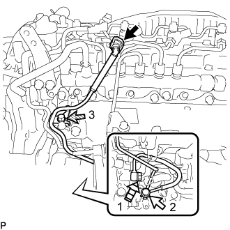
Text in Illustration Union Bolt Bolt 
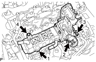
Supply Pump Hollow Screw Tighten the union bolt and bolt in the order shown in the illustration.
- Torque:
- union bolt
- 42 N*m { 428 kgf*cm, 31 ft.*lbf }
- bolt
- 10 N*m { 102 kgf*cm, 7 ft.*lbf }
-
Tighten the supply pump hollow screw in the order shown in the illustration.
- Torque:
- 42 N*m { 428 kgf*cm, 31 ft.*lbf }
-
Connect the No. 4 fuel pipe sub-assembly to the No. 1 fuel pipe Click here.
-
-
INSTALL FUEL PUMP MOTOR WIRE
-
Connect the fuel pump motor wire connector and install the fuel pump motor wire.
-
-
INSTALL FUEL INJECTION PUMP COVER SUB-ASSEMBLY
-
Install the fuel injection pump cover sub-assembly to the supply pump assembly.
-
-
INSTALL MANIFOLD STAY
-
Install the manifold stay with the 2 bolts.
- Torque:
- 21 N*m { 214 kgf*cm, 15 ft.*lbf }
-
Install the wiring harness clamp bracket with the bolt.
- Torque:
- 13 N*m { 128 kgf*cm, 9 ft.*lbf }
-
-
INSTALL WIRING HARNESS CLAMP BRACKET
-
Install the wiring harness clamp bracket with the bolt.
- Torque:
- 10 N*m { 102 kgf*cm, 7 ft.*lbf }
-
Attach the 2 wire harness clamps.
-
Connect the diesel throttle body assembly connector and pre-stroke control valve connector.
-
-
INSTALL NO. 2 FUEL PIPE
-
Install the No. 2 fuel pipe to the manifold stay with the bolt.
- Torque:
- 10 N*m { 102 kgf*cm, 7 ft.*lbf }
-
Connect the No. 1 fuel hose to the No. 2 fuel pipe, and slide the clamp to secure the hose.
-
-
INSTALL ENGINE OIL LEVEL DIPSTICK GUIDE
-
Apply a light coat of engine oil to a new O-ring and new grommet.
-
Install the O-ring and grommet to the engine oil level dipstick guide.
-
Install the engine oil level dipstick guide with the bolt.
- Torque:
- 10 N*m { 102 kgf*cm, 7 ft.*lbf }
-
Connect the vacuum hose to the intake manifold, and slide the clip to secure the hose.
-
Install the engine oil level dipstick.
-
-
INSTALL NO. 1 EGR COOLER AND NO. 2 EGR VALVE ASSEMBLY WITH ELECTRIC EGR CONTROL VALVE ASSEMBLY
-
Temporarily install the No. 1 EGR cooler and No. 2 EGR valve assembly with electric EGR control valve assembly to the intake manifold with the 4 bolts.
-
Tighten the 4 bolts in the order shown in the illustration.
Tech Tips
Make sure to tighten the bolts in the order.
- Torque:
- 21 N*m { 214 kgf*cm, 15 ft.*lbf }
-
-
INSTALL NO. 4 WATER BY-PASS PIPE SUB-ASSEMBLY
-
Install the No. 4 water by-pass pipe sub-assembly to the intake manifold with the 2 bolts.
- Torque:
- 10 N*m { 102 kgf*cm, 7 ft.*lbf }
-
Connect the water hose to the No. 2 EGR valve assembly, and slide the clamp to secure the hose.
-
Connect the No. 7 water by-pass hose to the No. 4 water by-pass pipe sub-assembly, and slide the clamp to secure the hose.
-
Connect the No. 6 water by-pass hose to the No. 4 water by-pass pipe sub-assembly, and slide the clamp to secure the hose.
-
-
INSTALL VACUUM CONTROL VALVE SET
-
Install the vacuum control valve set to the intake manifold with the 2 bolts.
- Torque:
- 10 N*m { 102 kgf*cm, 7 ft.*lbf }
-
Connect the 2 vacuum hoses to the vacuum control valve set and No. 2 EGR valve assembly.
-
Connect the connector to the vacuum control valve set.
-
-
INSTALL NO. 1 EGR PIPE SUB-ASSEMBLY
-
Using an E8 "TORX" socket wrench, install 2 new stud bolts to the exhaust manifold.
- Torque:
- 10 N*m { 102 kgf*cm, 7 ft.*lbf }
-
Install 2 new gaskets and the No. 1 EGR pipe sub-assembly to the exhaust manifold, electric EGR control valve assembly and No. 1 vacuum transmitting pipe sub-assembly with the bolt and 4 new nuts.
- Torque:
- for bolt
- 10 N*m { 102 kgf*cm, 7 ft.*lbf }
- for nut
- 29 N*m { 296 kgf*cm, 21 ft.*lbf }
-
-
INSTALL CONNECTING WIRE
-
Attach the 2 clamps and install the connecting wire to the bracket.
-
Connect the connector to the common rail assembly.
-
-
INSTALL NO. 3 WATER BY-PASS PIPE SUB-ASSEMBLY
-
Install the No. 3 water by-pass pipe sub-assembly to the No. 1 EGR cooler with the 2 bolts.
- Torque:
- 10 N*m { 102 kgf*cm, 7 ft.*lbf }
-
Connect the No. 9 water by-pass hose to the electric EGR control valve assembly, and slide the clamp to secure the hose.
-
Connect the No. 8 water by-pass hose to the No. 3 water by-pass pipe sub-assembly, and slide the clamp to secure the hose.
-
Connect the No. 4 fuel hose to the No. 3 water by-pass pipe sub-assembly.
-
-
INSTALL NO. 2 EGR PIPE
-
Install 2 new gaskets and No. 2 EGR pipe to the electric EGR control valve assembly and the intake manifold with the 4 nuts.
- Torque:
- 29 N*m { 296 kgf*cm, 21 ft.*lbf }
-
-
INSTALL EGR VALVE BRACKET
-
Install the EGR valve bracket to the electric EGR control valve assembly and intake manifold with the bolt and nut.
- Torque:
- 21 N*m { 214 kgf*cm, 15 ft.*lbf }
-
-
INSTALL DIESEL TURBO PRESSURE SENSOR
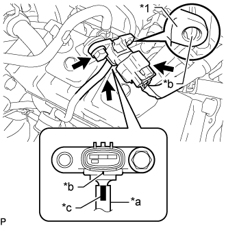
Text in Illustration *1 Diesel Turbo Pressure Sensor *a Vacuum Hose *b Protrusion *c Paint Mark
-
Connect the vacuum hose to the diesel turbo pressure sensor.
Note
Connect the vacuum hose so that the paint mark on the vacuum hose is aligned with the protrusions of the diesel turbo pressure sensor as shown in the illustration.
-
Install the diesel turbo pressure sensor with the bolt.
- Torque:
- 10 N*m { 102 kgf*cm, 7 ft.*lbf }
Note
Make sure the protrusion is inserted into the hole of the diesel turbo pressure sensor.
-
Connect the diesel turbo pressure sensor connector.
-
-
INSTALL GAS FILTER
-
Install the gas filter to the gas filter bracket.
-
Connect the 2 vacuum hoses to the turbo pressure sensor and intake manifold.
-
-
INSTALL ENGINE COVER BRACKET
-
Install the EGR valve bracket to the electric EGR control valve assembly and intake manifold with the bolt and nut.
- Torque:
- 21 N*m { 214 kgf*cm, 15 ft.*lbf }
-
-
INSTALL PIPE CLAMP
-
Install the pipe clamp to the engine cover bracket with the 3 bolts.
- Torque:
- 10 N*m { 102 kgf*cm, 7 ft.*lbf }
-
-
TEMPORARILY INSTALL NO. 2 VACUUM PIPE
-
Install a new clamp to the pipe clamp.
-
Temporarily install the No. 2 vacuum pipe to the exhaust manifold converter sub-assembly.
-
-
TEMPORARILY INSTALL NO. 1 VACUUM PIPE
-
Temporarily install the No. 1 vacuum pipe to the exhaust manifold converter sub-assembly.
-
Install a new clamp to the No. 1 vacuum pipe and No. 2 vacuum pipe with the nut.
- Torque:
- 6.0 N*m { 61 kgf*cm, 53 in.*lbf }
-
-
TIGHTEN NO. 2 VACUUM PIPE
-
Text in Illustration *a Torque Wrench Fulcrum Length Using a 17 mm union nut wrench, tighten the No. 2 vacuum pipe.
Torque Specified tightening torque 48 N*m {489 kgf*cm, 35 ft.*lbf} Tech Tips
-
Calculate the torque wrench reading when changing the fulcrum length of the torque wrench Click here.
-
When using a union nut wrench (fulcrum length of 30 mm (1.18 in.)) + torque wrench (fulcrum length of 255 mm (10.0 in.)): 43 N*m (437 kgf*cm, 32 ft.*lbf)
-
-
-
TIGHTEN NO. 1 VACUUM PIPE
-
Text in Illustration *a Torque Wrench Fulcrum Length Using a 17 mm union nut wrench, tighten the No. 1 vacuum pipe.
Torque Specified tightening torque 48 N*m {489 kgf*cm, 35 ft.*lbf} Tech Tips
-
Calculate the torque wrench reading when changing the fulcrum length of the torque wrench Click here.
-
When using a union nut wrench (fulcrum length of 30 mm (1.18 in.)) + torque wrench (fulcrum length of 255 mm (10.0 in.)): 43 N*m (437 kgf*cm, 32 ft.*lbf)
-
-
-
INSTALL EXHAUST GAS TEMPERATURE SENSOR
-

Text in Illustration *a Torque Wrench Fulcrum Length Using a 14 mm union nut wrench, install the No. 3 exhaust gas temperature sensor to the exhaust manifold converter sub-assembly.
Torque Specified tightening torque 30 N*m {306 kgf*cm, 22 ft.*lbf} Note
-
If the No. 3 exhaust gas temperature sensor is dropped, replace it with a new.
-
When reusing the No. 3 exhaust gas temperature sensors, clean the screws and apply anti-seize compound before installing the No. 3 exhaust gas temperature sensor.
Tech Tips
-
The connector color of the No. 3 exhaust gas temperature sensor is gray.
-
Calculate the torque wrench reading when changing the fulcrum length of the torque wrench Click here.
-
When using a union nut wrench (fulcrum length of 25 mm (0.984 in.)) + torque wrench (fulcrum length of 180 mm (7.09 in.)): 26 N*m (268 kgf*cm, 19 ft.*lbf)
-
-
Text in Illustration *a Torque Wrench Fulcrum Length Using a 14 mm union nut wrench, install the No. 2 exhaust gas temperature sensor to the exhaust manifold converter sub-assembly.
Torque Specified tightening torque 30 N*m {306 kgf*cm, 22 ft.*lbf} Note
-
If the No. 2 exhaust gas temperature sensor is dropped, replace it with a new.
-
When reusing the No. 2 exhaust gas temperature sensors, clean the screws and apply anti-seize compound before installing the No. 2 exhaust gas temperature sensor.
Tech Tips
-
The connector color of the No. 2 exhaust gas temperature sensor is black.
-
Calculate the torque wrench reading when changing the fulcrum length of the torque wrench Click here.
-
When using a union nut wrench (fulcrum length of 25 mm (0.984 in.)) + torque wrench (fulcrum length of 180 mm (7.09 in.)): 26 N*m (268 kgf*cm, 19 ft.*lbf)
-
-
Text in Illustration *a Torque Wrench Fulcrum Length Using a 14 mm union nut wrench, install the exhaust gas temperature sensor to the exhaust manifold converter sub-assembly.
Torque Specified tightening torque 30 N*m {306 kgf*cm, 22 ft.*lbf} Note
-
If the exhaust gas temperature sensor is dropped, replace it with a new.
-
When reusing the exhaust gas temperature sensors, clean the screws and apply anti-seize compound before installing the exhaust gas temperature sensor.
Tech Tips
-
The connector color of the exhaust gas temperature sensor is white.
-
Calculate the torque wrench reading when changing the fulcrum length of the torque wrench Click here.
-
When using a union nut wrench (fulcrum length of 25 mm (0.984 in.)) + torque wrench (fulcrum length of 180 mm (7.09 in.)): 26 N*m (268 kgf*cm, 19 ft.*lbf)
-
-
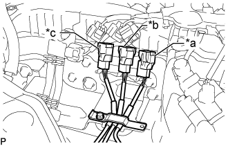
Text in Illustration *a White *b Black *c Gray Attach the 3 colored connectors to the pipe clamp in the positions shown in the illustration.
-
Close the clamp of the pipe clamp, and install the bolt.
- Torque:
- 10 N*m { 102 kgf*cm, 7 ft.*lbf }
Note
Arrange the exhaust gas temperature sensor wires so that they do not contact each other.
-
Connect the No. 3 exhaust gas temperature sensor to the No. 1 vacuum pipe.
- Torque:
- 10 N*m { 102 kgf*cm, 7 ft.*lbf }
-
Connect the 3 connectors to the 3 exhaust gas temperature sensors.
-
-
INSTALL DIFFERENTIAL PRESSURE SENSOR
-
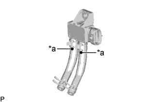
Text in Illustration *a Paint Mark Install the 2 air hoses to the differential pressure sensor, and slide the 2 clamps to secure the 2 hoses.
Tech Tips
Make sure the paint mark of the air hose side the differential pressure sensor.
-
Connect the 2 air hoses to the No. 1 vacuum pipe and No. 2 vacuum pipe, and slide the 2 clamps to secure the 2 hoses.
-
Install the differential pressure sensor to the pipe clamp with the bolt.
- Torque:
- 10 N*m { 102 kgf*cm, 7 ft.*lbf }
-
Connect the connector to the differential pressure sensor.
-
-
INSTALL NO. 2 WATER BY-PASS PIPE
-
Install the No. 2 water by-pass pipe with the 2 bolts.
- Torque:
- 10 N*m { 102 kgf*cm, 7 ft.*lbf }
-
-
INSTALL DIESEL THROTTLE BODY ASSEMBLY
-
Connect the connector to install the emission control valve wire to the diesel throttle body assembly.
-
Install a new gasket and the diesel throttle body assembly with the 2 bolts and 2 nuts.
- Torque:
- 10 N*m { 102 kgf*cm, 7 ft.*lbf }
-
Connect the connector and clamp.
-
-
INSTALL INTERCOOLER AIR TUBE
-
Install the intercooler air tube to the diesel throttle body assembly and tighten the hose clamp.
- Torque:
- 6.0 N*m { 61 kgf*cm, 53 in.*lbf }
-
Connect the connector to the intake air temperature sensor.
-
Install the air tube support bracket with the 3 bolts.
- Torque:
- 6.0 N*m { 61 kgf*cm, 53 in.*lbf }
-
-
INSTALL ENGINE WIRE
-
INSTALL ENGINE ASSEMBLY