OIL PUMP REMOVAL

Note
-
When replacing the parts in the following chart (A), replace the No. 1 injection pipe sub-assembly, No. 2 injection pipe sub-assembly and/or fuel inlet pipe sub-assembly with new ones.
Replaced Parts (A) Pipes Requiring New Replacement Injector assembly (including shuffling the injector assemblies between the cylinders)
-
No. 1 injection pipe sub-assembly
-
No. 2 injection pipe sub-assembly
Supply pump assembly Fuel inlet pipe sub-assembly
-
Common rail assembly
-
Cylinder block sub-assembly
-
Cylinder head sub-assembly
-
Cylinder head gasket
-
Timing chain case assembly
-
Fuel inlet pipe sub-assembly
-
No. 1 injection pipe sub-assembly
-
No. 2 injection pipe sub-assembly
-
-
After removing the No. 1 injection pipe sub-assembly, No. 2 injection pipe sub-assembly and/or fuel inlet pipe sub-assembly, clean them with a brush and compressed air.
-
The injector assembly is a precision instrument. Do not use the injector assembly if it is struck or dropped.
-
Make sure foreign matter does not enter the fuel path.
-
The supply pump assembly is a precision instrument. Do not use the supply pump assembly if it is struck or dropped.
-
Hold the supply pump assembly itself during removal and installation. Do not hold the pre-stroke control valve or fuel pipe, etc.
-
REMOVE ENGINE ASSEMBLY
-
REMOVE ENGINE WIRE
-
REMOVE INTERCOOLER AIR TUBE
-
Remove the 2 bolts and air tube support bracket.
-
Disconnect the connector from the intake air temperature sensor.
-
Loosen the hose clamp and remove the intercooler air tube from the diesel throttle body assembly.
-
-
REMOVE DIESEL THROTTLE BODY ASSEMBLY
-
Disconnect the connector and clamp.
-
Remove the 2 bolts, 2 nuts, diesel throttle body and gasket.
-
Disconnect the connector to remove the emission control valve wire from the diesel throttle body assembly.
-
-
REMOVE NO. 2 WATER BY-PASS PIPE
-
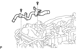
Remove the 2 bolts and No. 2 water by-pass pipe.
-
-
REMOVE DIFFERENTIAL PRESSURE SENSOR
-
Disconnect the connector from the differential pressure sensor.
-
Remove the bolt and differential pressure sensor from the pipe clamp.
-
Slide the 2 clamps and disconnect the 2 air hoses from the No. 1 vacuum pipe and No. 2 vacuum pipe.
-
Slide the 2 clamps and remove the 2 air hoses from the differential pressure sensor.
-
-
REMOVE EXHAUST GAS TEMPERATURE SENSOR
CAUTION:
To prevent burns, do not touch the engine, exhaust manifold or other high temperature components while the engine is hot.
-
Disconnect the 3 connectors from the 3 exhaust gas temperature sensors.
-
Remove the nut and disconnect the No. 3 exhaust gas temperature sensor from the No. 1 vacuum pipe.
-
Remove the bolt and open the clamp of the pipe clamp.
-
Detach the 3 connectors from the pipe clamp.
-
Using a 14 mm union nut wrench, remove the exhaust gas temperature sensor from the exhaust manifold converter sub-assembly.
-
Using a 14 mm union nut wrench, remove the No. 2 exhaust gas temperature sensor from the exhaust manifold converter sub-assembly.
-
Using a 14 mm union nut wrench, remove the No. 3 exhaust gas temperature sensor from the exhaust manifold converter sub-assembly.
-
-
REMOVE NO. 1 VACUUM PIPE
-
Remove the nut and clamp from the No. 1 vacuum pipe and No. 2 vacuum pipe.
-
Using a 17 mm union nut wrench, remove the No. 1 vacuum pipe from the exhaust manifold converter sub-assembly.
-
-
REMOVE NO. 2 VACUUM PIPE
-
Using a 17 mm union nut wrench, remove the No. 2 vacuum pipe from the exhaust manifold converter sub-assembly.
-
Remove the clamp from the pipe clamp.
-
-
REMOVE PIPE CLAMP
-
Remove the 3 bolts and pipe clamp from the engine cover bracket.
-
-
REMOVE ENGINE COVER BRACKET
-
Remove the 2 bolts and engine cover bracket from the cylinder head sub-assembly.
-
-
REMOVE GAS FILTER
-
Disconnect the 2 vacuum hoses from the turbo pressure sensor and intake manifold.
-
Remove the gas filter from the gas filter bracket.
-
-
REMOVE DIESEL TURBO PRESSURE SENSOR
-
Disconnect the diesel turbo pressure sensor connector.
-
Remove the bolt and diesel turbo pressure sensor.
-
Disconnect the vacuum hose from the diesel turbo pressure sensor.
-
-
REMOVE EGR VALVE BRACKET
-
Remove the bolt, nut and EGR valve bracket from the electric EGR control valve assembly and intake manifold.
-
-
REMOVE NO. 2 EGR PIPE
-
Remove the bolt, 4 nuts and No. 2 EGR pipe from the electric EGR control valve assembly and intake manifold.
-
Remove the 2 gaskets.
-
-
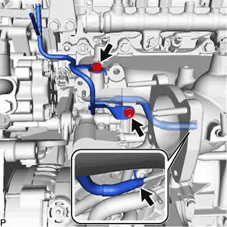
REMOVE NO. 3 WATER BY-PASS PIPE SUB-ASSEMBLY
-
Disconnect the No. 4 fuel hose from the No. 3 water by-pass pipe sub-assembly.
-
Slide the clamp and disconnect the No. 8 water by-pass hose from the No. 3 water by-pass pipe sub-assembly.
-
Slide the clamp and disconnect the No. 9 water by-pass hose from the electric EGR control valve assembly.
-
Remove the 2 bolts and No. 3 water by-pass pipe sub-assembly from the No. 1 EGR cooler.
-
-
REMOVE CONNECTING WIRE
-
Disconnect the connector from the common rail assembly.
-
Detach the 2 clamps and remove the connecting wire from the bracket.
-
-
REMOVE NO. 1 EGR PIPE SUB-ASSEMBLY
-

Remove the 4 nuts, bolt and No. 1 EGR pipe sub-assembly from the exhaust manifold, electric EGR control valve assembly and No. 1 vacuum transmitting pipe sub-assembly.
-
Remove the 2 gaskets from the exhaust manifold and electric EGR control valve assembly.
-
Using an E8 "TORX" socket wrench, remove the 2 stud bolts from the exhaust manifold.
-
-
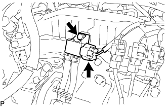
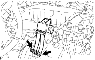
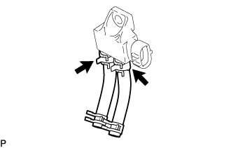
REMOVE VACUUM CONTROL VALVE SET
-
Disconnect the connector from the vacuum control valve set.
-
Disconnect the 2 vacuum hoses from the vacuum control valve set and No. 2 EGR valve assembly.
-
Remove the 2 bolts and vacuum control valve set from the intake manifold.
-
-
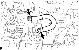
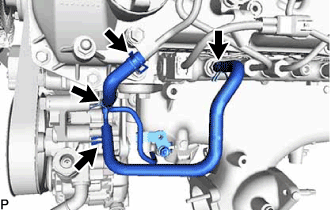
REMOVE NO. 4 WATER BY-PASS PIPE SUB-ASSEMBLY
-
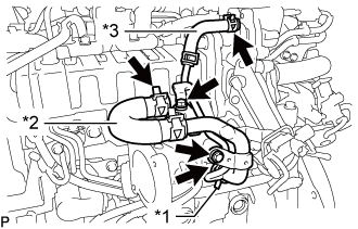
Text in Illustration *1 No. 6 Water By-pass Hose *2 No. 7 Water By-pass Hose *3 Water Hose Slide the clamp and disconnect the No. 6 water by-pass hose from the No. 4 water by-pass pipe sub-assembly.
-
Slide the clamp and disconnect the No. 7 water by-pass hose from the No. 4 water by-pass pipe sub-assembly.
-
Slide the clamp and disconnect the water hose from the No. 2 EGR valve assembly.
-
Remove the 2 bolts and No. 4 water by-pass pipe sub-assembly from the intake manifold.
-
-
REMOVE NO. 1 EGR COOLER AND NO. 2 EGR VALVE ASSEMBLY WITH ELECTRIC EGR CONTROL VALVE ASSEMBLY
-
Remove the 4 bolts and No. 1 EGR cooler and No. 2 EGR valve assembly with electric EGR control valve assembly from the intake manifold.
-
-
REMOVE ENGINE OIL LEVEL DIPSTICK GUIDE
-
Remove the engine oil level dipstick.
-
Slide the clip and disconnect vacuum hose from the intake manifold.
-
Remove the bolt and engine oil level dipstick guide.
-
Remove the O-ring and grommet from the engine oil level dipstick guide.
-
-
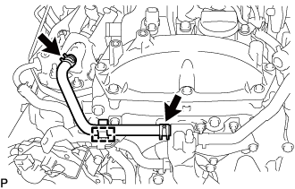
REMOVE NO. 2 FUEL PIPE
-
Slide the clamp and disconnect the No. 1 fuel hose from the No. 2 fuel pipe.
-
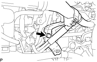
Remove the bolt and No. 2 fuel pipe from the manifold stay.
-
-
REMOVE WIRING HARNESS CLAMP BRACKET
-
Disconnect the diesel throttle body assembly connector and pre-stroke control valve connector.
-
Detach the 2 wire harness clamps.
-
Remove the bolt and wiring harness clamp bracket.
-
-
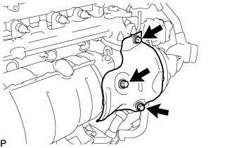
REMOVE MANIFOLD STAY
-
Remove the bolt and disconnect the wiring harness clamp bracket from the manifold stay.
-
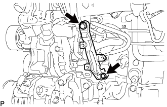
Remove the 2 bolts and manifold stay.
-
-
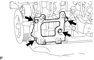
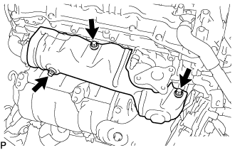
REMOVE FUEL INJECTION PUMP COVER SUB-ASSEMBLY
-
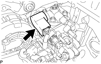
Remove the fuel injection pump cover sub-assembly from the supply pump assembly.
-
-
REMOVE FUEL PUMP MOTOR WIRE
-
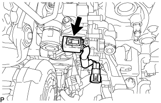
Disconnect the fuel pump motor wire connector and remove the fuel pump motor wire.
-
-
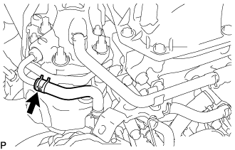
REMOVE NO. 2 FUEL HOSE
-
Slide the 2 clips and remove the No. 2 fuel hose from the supply pump assembly and No. 3 nozzle leakage pipe assembly.
-
-
REMOVE NO. 1 FUEL HOSE
-
Slide the 2 clips and remove the No. 1 fuel hose from the supply pump assembly and No. 2 fuel pipe.
-
-
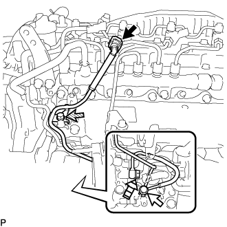
REMOVE NO. 4 FUEL PIPE SUB-ASSEMBLY
-
Disconnect the No. 4 fuel pipe sub-assembly from the No. 1 fuel pipe Click here.
Text in Illustration 
Union Bolt 
Bolt 
Supply Pump Hollow Screw -
Remove the bolt from the intake manifold.
-
Remove the union bolts and gasket from the supply pump assembly.
-
Remove the supply pump hollow screw and gasket from the supply pump assembly.
-
-
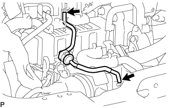
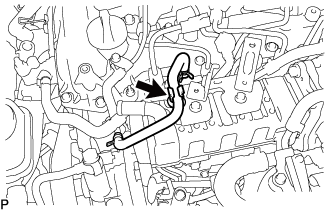
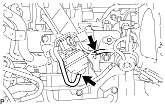
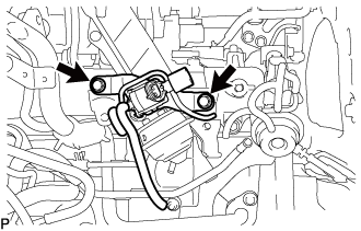
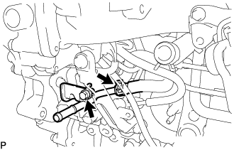
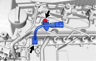
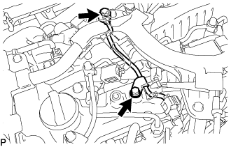
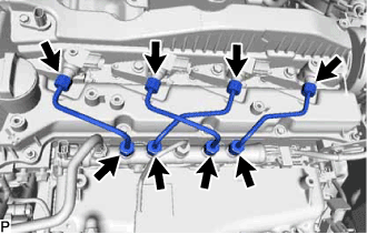
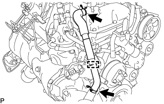
REMOVE FUEL INLET PIPE SUB-ASSEMBLY
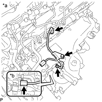
Text in Illustration *a Common Rail Assembly Side *b Fuel Supply Pump Assembly Side
-
Remove the 2 bolts, No. 1 injection pipe clamp and No. 2 injection pipe clamp.
-
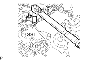
Using SST, loosen the fuel inlet pipe sub-assembly union nut of the common rail assembly side.
- SST
- 09245-11010
Note
If the No. 1 or No. 2 injection pipe clamp is removed from the inlet pipe sub-assembly, replace the No. 1 or No. 2 injection clamp with a new one.
-
Using a 19 mm union nut wrench, loosen the inlet pipe sub-assembly union nut of the fuel supply pump assembly side.
-
-
REMOVE NO. 2 NOZZLE LEAKAGE PIPE ASSEMBLY
-
Slide the 2 clamps and remove the No. 4 fuel hose from the No. 2 nozzle leakage pipe assembly and common rail assembly.
-
Slide the 2 clamps and remove the No. 5 fuel hose from the No. 1 nozzle leakage pipe assembly and No. 2 nozzle leakage pipe assembly.
-
Slide the clamp and disconnect the No. 6 fuel hose from the No. 3 nozzle leakage pipe assembly.
-
Remove the 2 bolts and No. 2 nozzle leakage pipe assembly.
-
-
REMOVE INTAKE MANIFOLD
-
Remove the bolt and disconnect the wire harness bracket.
-
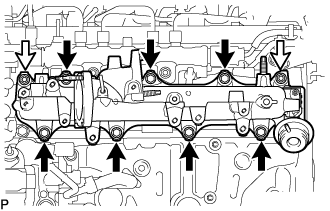
Remove the 7 bolts, 2 nuts, intake manifold and gasket.
Text in Illustration 
Bolt Nut
-
-
REMOVE WIRING HARNESS CLAMP BRACKET
-
Disconnect the pressure discharge valve connector from the common rail assembly.
-
Remove the bolt and wiring harness clamp bracket from the cylinder head cover sub-assembly.
-
-
REMOVE NO. 1 FUEL PIPE
-
Remove the bolt, union bolt and gasket and disconnect the No. 1 fuel pipe from the cylinder head cover sub-assembly and exhaust fuel addition injector assembly.
-
Disconnect the No. 4 fuel pipe and remove the No. 1 fuel pipe Click here.
-
-
REMOVE NOZZLE LEAKAGE PIPE ASSEMBLY
Note
After removing the No. 1 and No. 2 injection pipe sub-assemblies, cover the common rail assembly with electrical tape to prevent dirt or foreign objects from entering the pipe inlet. Also, protect the injector inlets with electrical tape or plastic bags.
-
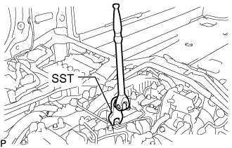
Using SST, loosen the No. 1 and No. 2 injection pipe sub-assemblies and 8 union nuts of the fuel injector assembly side and common rail assembly side.
- SST
- 09245-11010
-
Remove the 2 No. 1 injection pipe sub-assemblies and 2 No. 2 injection pipe sub-assemblies.
Note
When removing the No. 1 injection pipe sub-assembly and No. 2 injection pipe sub-assembly, store the injector assemblies in the correct order so that they can be returned to their original locations when reassembling.
-
-
REMOVE WIRING HARNESS CLAMP BRACKET
-
for Upper Side:
Remove the bolt and wiring harness clamp bracket from the cylinder head cover sub-assembly.
-
for Rear Side:
Remove the bolt and wiring harness clamp bracket from the cylinder block sub-assembly.
-
-
REMOVE NO. 1 AND NO. 2 INJECTION PIPE SUB-ASSEMBLY
Note
After removing the No. 1 and No. 2 injection pipe sub-assemblies, cover the common rail assembly with electrical tape to prevent dirt or foreign objects from entering the pipe inlet. Also, protect the injector inlets with electrical tape or plastic bags.
-
Using SST, loosen the No. 1 and No. 2 injection pipe sub-assemblies and 8 union nuts of the fuel injector assembly side and common rail assembly side.
- SST
- 09245-11010
-
Remove the 2 No. 1 injection pipe sub-assemblies and 2 No. 2 injection pipe sub-assemblies.
Note
When removing the No. 1 injection pipe sub-assembly and No. 2 injection pipe sub-assembly, store the injector assemblies in the correct order so that they can be returned to their original locations when reassembling.
-
-
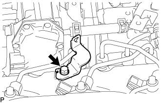
REMOVE HOSE BRACKET
-
Remove the 2 bolts and bracket from the cylinder head sub-assembly.
-
-
REMOVE COOLER COMPRESSOR ASSEMBLY
-
REMOVE NO. 1 COMPRESSOR MOUNTING BRACKET
-
Remove the 4 bolts and No. 1 compressor mounting bracket from the cylinder block sub-assembly, timing chain case assembly and timing chain cover sub-assembly.
-
-
REMOVE PCV HOSE
-
Slide the 2 clips, detach the clamp and remove the PCV hose.
-
-
REMOVE NO. 5 WATER BY-PASS HOSE
-
Slide the 2 clamps and disconnect the No. 5 water by-pass hose from the No. 1 injector holder and water outlet sub-assembly.
-
Detach the clamp and remove the No. 5 water by-pass hose from the hose clamp.
-
-
REMOVE NO. 4 WATER BY-PASS HOSE
-
Slide the clamp and disconnect the No. 4 water by-pass hose from the No. 1 injector holder.
-
-
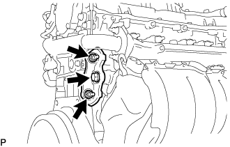
REMOVE NO. 1 INJECTOR HOLDER
-
Disconnect the connector from the exhaust fuel addition injector assembly.
-
Remove the 3 nuts and No. 1 injector holder from the exhaust manifold.
-
-
REMOVE NO. 2 EXHAUST MANIFOLD HEAT INSULATOR
-
Remove the 3 nuts and No. 2 exhaust manifold heat insulator from the No. 1 injector holder.
-
Remove the gasket.
-
-
REMOVE AIR FUEL RATIO SENSOR
CAUTION:
To prevent burns, do not touch the engine, exhaust manifold or other high temperature components while the engine is hot.
-
Disconnect the connector.
-
Using SST, remove the air fuel ratio sensor.
- SST
- 09224-00012
-
-
REMOVE NO. 1 EXHAUST MANIFOLD HEAT INSULATOR
-
Remove the 3 bolts and No. 1 exhaust manifold heat insulator from the exhaust manifold.
-
-
REMOVE NO. 1 TURBO INSULATOR
-
Remove the 3 bolts and No. 1 turbo insulator from the exhaust manifold and turbocharger sub-assembly.
-
-
REMOVE NO. 2 EXHAUST PIPE SUPPORT STAY
-
Remove the bolt, 2 nuts and No. 2 exhaust pipe support stay from the cylinder block sub-assembly and exhaust manifold converter sub-assembly.
-
-
REMOVE EXHAUST PIPE SUPPORT STAY
-
Remove the 3 bolts and exhaust pipe support stay from the cylinder block sub-assembly and exhaust manifold converter sub-assembly.
-
-
REMOVE EXHAUST MANIFOLD CONVERTER SUB-ASSEMBLY
-
Remove the nut, exhaust pipe clamp and exhaust manifold converter sub-assembly from the turbocharger sub-assembly.
-
Remove the gasket.
-
-
REMOVE FRONT ENGINE MOUNTING INSULATOR RH
-
REMOVE FRONT ENGINE MOUNTING INSULATOR
-
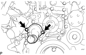
REMOVE NO. 1 WATER BY-PASS PIPE
-
Remove the 2 bolts, No. 1 water by-pass pipe and gasket from the timing chain cover sub-assembly.
-
-
REMOVE NO. 1 AND NO. 2 TURBO WATER HOSE
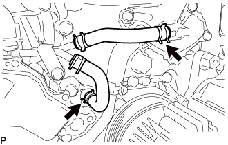
-
Slide the clip and disconnect the No. 1 turbo water hose from the water pump assembly.
-
Slide the clip and disconnect the No. 2 turbo water hose from the water outlet sub-assembly.
-
-
REMOVE TURBOCHARGER STAY
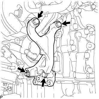
-
Remove the 3 bolts, nut and turbocharger stay.
-
-
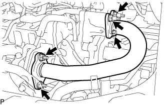
REMOVE TURBO OIL OUTLET PIPE
-
Slide the 2 clips and disconnect the turbo oil outlet hose from the turbo oil outlet pipe.
-
Remove the 2 bolts, turbo oil outlet pipe and gasket.
-
-
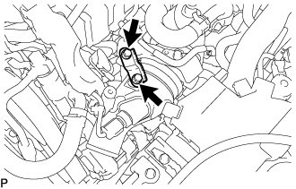
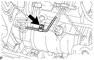
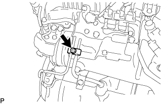
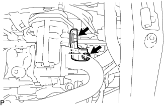
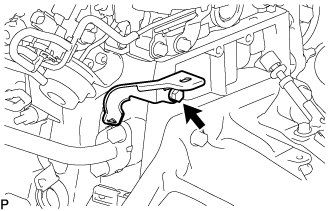
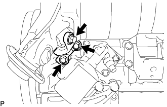
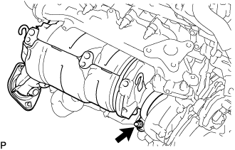
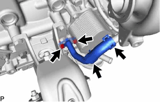
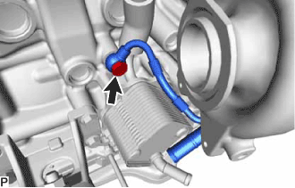
REMOVE TURBO OIL INLET PIPE SUB-ASSEMBLY
-
Remove the union bolt and gasket.
-
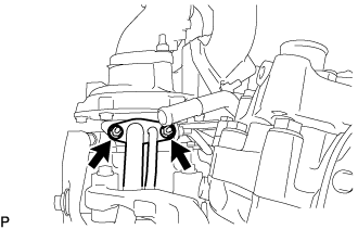
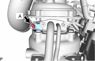
Remove the 2 nuts and turbo oil inlet pipe sub-assembly.
Note
Do not loosen the nut labeled A.
-
Remove the gasket.
-
-
REMOVE TURBOCHARGER SUB-ASSEMBLY
-
Remove the 3 nuts and turbocharger sub-assembly.
-
Remove the gasket from the turbocharger sub-assembly.
-
-
REMOVE NO. 2 WATER BY-PASS PIPE SUB-ASSEMBLY
-
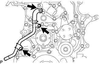
Slide the clamp and disconnect the No. 3 water by-pass hose from the water outlet sub-assembly.
-
Remove the 2 bolts and No. 2 water by-pass pipe sub-assembly from the engine water pump assembly and water inlet.
-
-
REMOVE WATER OUTLET SUB-ASSEMBLY
-
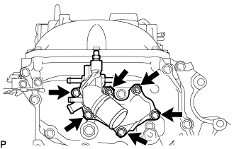
Remove the 4 bolts, 2 nuts and water outlet sub-assembly from the timing chain cover sub-assembly.
-
Remove the gasket from the timing chain cover sub-assembly.
-
-
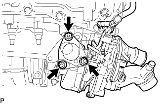
REMOVE WATER INLET
-
Remove the 2 bolts and water inlet from the engine water pump assembly.
-
-
REMOVE THERMOSTAT
-
Remove the thermostat from the engine water pump assembly.
-
Remove the gasket from the thermostat.
-
-
REMOVE NO. 1 IDLER PULLEY SUB-ASSEMBLY
-
Remove the bolt and No. 1 idler pulley sub-assembly from the generator bracket sub-assembly.
-
-
REMOVE V-RIBBED BELT TENSIONER ASSEMBLY
-
Remove the 3 bolts and V-ribbed belt tensioner assembly from the timing chain cover sub-assembly.
-
-
REMOVE CRANKSHAFT PULLEY COVER
-
Remove the 4 bolts and crankshaft pulley cover from the crankshaft pulley.
-
-
REMOVE CRANKSHAFT PULLEY
-
Using SST, hold the crankshaft pulley and loosen the pulley bolt.
- SST
- 09213-58014
- 09330-00021
Tech Tips
Make sure to leave the pulley bolt screwed into the crankshaft by 2 or 3 threads.
-
Using SST, remove the pulley bolt and crankshaft pulley from the crankshaft.
- SST
- 09950-50013 ( 09951-05010, 09952-05010, 09953-05020, 09954-05021 )
-
-
REMOVE NO. 1 ENGINE HANGER
-
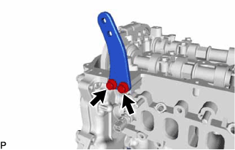
Remove the 2 bolts and No. 1 engine hanger from the cylinder head sub-assembly.
-
-
REMOVE GENERATOR BRACKET SUB-ASSEMBLY
-
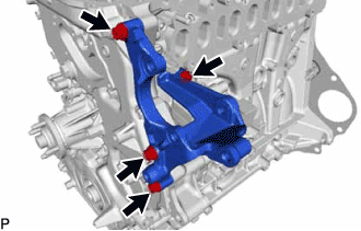
Remove the 4 bolts and generator bracket sub-assembly from the cylinder head sub-assembly and timing chain case assembly.
-
-
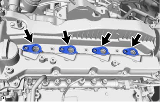
REMOVE INJECTOR ASSEMBLY
-
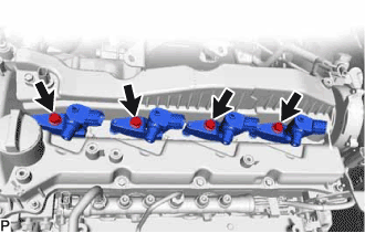
Remove the 4 nozzle holder clamp bolts, 4 washers and 4 nozzle holder clamps.
-
Remove the 4 fuel injector assemblies and 4 injection nozzle seats from the cylinder head sub-assembly.
Note
When removing the injector assembly, store the injector assemblies in the correct order so that they can be returned to their original locations when reassembling.
-
Remove the O-ring from each injector assembly.
-
-
REMOVE NOZZLE HOLDER GASKET
-
Remove the 4 nozzle holder gaskets from the cylinder head cover sub-assembly.
-
-
REMOVE CAMSHAFT POSITION SENSOR
-
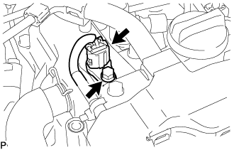
Disconnect the camshaft position sensor connector.
-
Remove the bolt and camshaft position sensor from the cylinder head cover sub-assembly.
-
-
REMOVE CYLINDER HEAD COVER SUB-ASSEMBLY
-
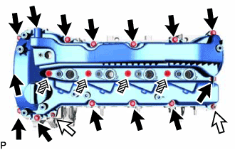
Remove the 14 bolts, 4 nozzle holder clamp seats, 2 nuts and cylinder head cover sub-assembly from the cylinder head sub-assembly.
Text in Illustration Bolt Nut Nozzle Holder Clamp Seat -
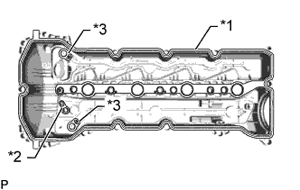
Text in Illustration *1 Cylinder Head Cover Gasket *2 No. 2 Cylinder Head Cover Gasket *3 Camshaft Bearing Cap Oil Hole Gasket Remove the cylinder head cover gasket, No. 2 cylinder head cover gasket and 2 camshaft bearing cap oil hole gaskets from the cylinder head cover sub-assembly.
-
-
REMOVE ENGINE OIL LEVEL SENSOR
-
Disconnect the engine oil level sensor connector.
-
Remove the 4 bolts and engine oil level sensor from the oil pan sub-assembly.
-
-
REMOVE OIL PAN SUB-ASSEMBLY
-
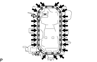
Remove the 2 nuts and 23 bolts.
Text in Illustration Bolt Nut -
Insert the blade of an oil pan seal cutter between the oil pan sub-assembly and cylinder block sub-assembly, cut off the applied sealer and remove the oil pan sub-assembly.
Note
-
Be careful not to damage the contact surfaces of the oil pan sub-assembly and cylinder block sub-assembly.
-
Be careful not to damage the cylinder block sub-assembly flange.
-
-
-
SET NO. 1 CYLINDER TO TDC/COMPRESSION
-
Temporarily install the crankshaft pulley and crankshaft pulley set bolt to the crankshaft.
-
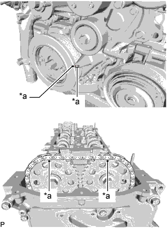
Text in Illustration *a Timing Mark Align the timing mark of the crankshaft pulley and timing chain cover sub-assembly by rotating the crankshaft clockwise.
-
Make sure that the timing mark of the camshaft timing sprocket is at the top.
Tech Tips
If the timing mark is not at the top, turn the crankshaft pulley 1 revolution so that the timing mark is at the top (set the No. 1 piston to TDC/compression).
-
-
REMOVE FAN PULLEY
-
Remove the 8 bolts, engine water pump assembly and gasket from the timing chain case assembly.
-
-
REMOVE ENGINE WATER PUMP ASSEMBLY
-
Remove the 8 bolts, engine water pump assembly and gasket from the timing chain case assembly.
-
-
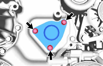
REMOVE TIMING CHAIN COVER PLATE
-
Remove the 3 bolts and timing chain cover plate.
-
Remove the gasket.
-
-
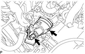
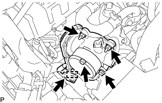
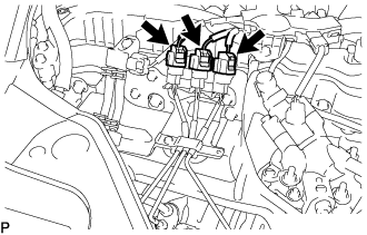
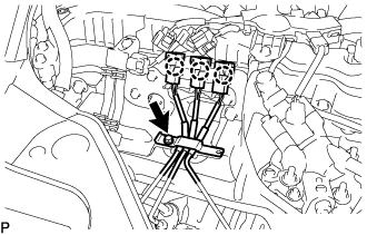
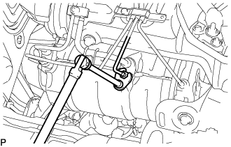
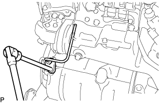
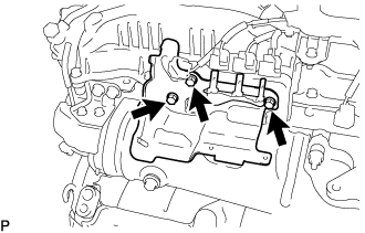
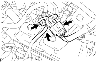
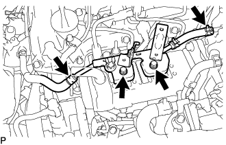
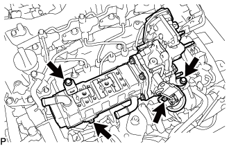
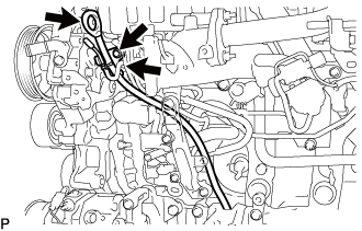
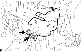
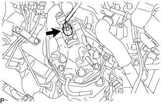
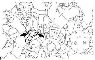
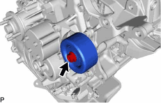
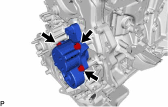
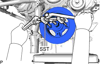
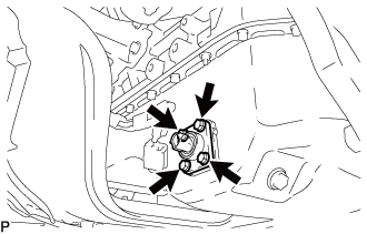
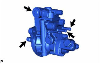
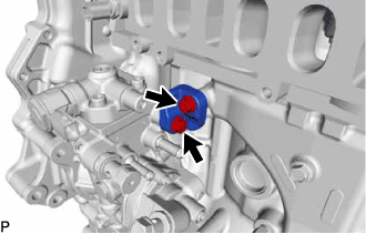
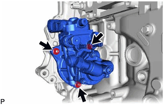
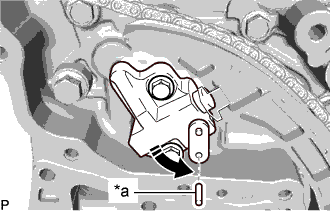
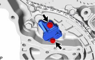
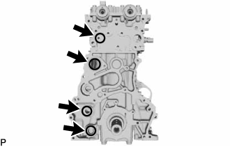
REMOVE SUPPLY PUMP ASSEMBLY
Note
Do not hold the supply pump assembly by the parts indicated by the arrows in the illustration.
-
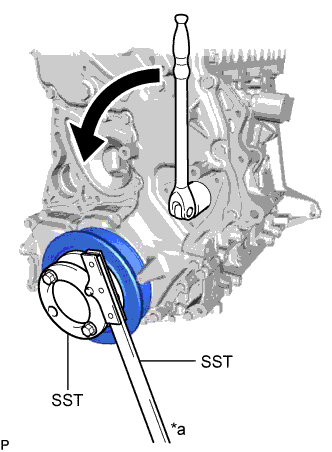
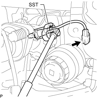
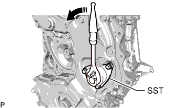
Text in Illustration *a Hold Turn Using SST, hold the crankshaft pulley and loosen the supply pump shaft nut.
- SST
- 09213-58014 ( 91551-80840 )
- 09330-00021
Note
Do not excessively loosen the supply pump shaft nut, otherwise SST cannot be installed.
Tech Tips
Rotate the supply pump shaft nut once to loosen it.
-
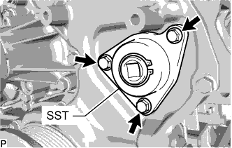
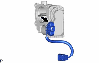
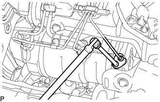
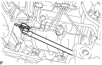
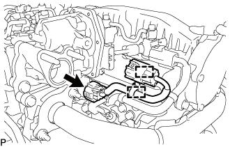
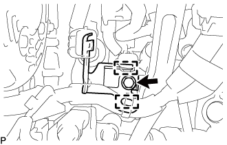
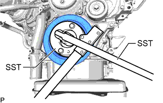
Text in Illustration *a Engine Front Side *b Engine Rear Side *c Hexagonal Portion Install SST to the timing chain cover sub-assembly with the 3 bolts.
- SST
- 09241-11010
- Torque:
- 10 N*m { 102 kgf*cm, 7 ft.*lbf }
Tech Tips
-
Make sure that the installation direction of SST is as shown in the illustration.
-
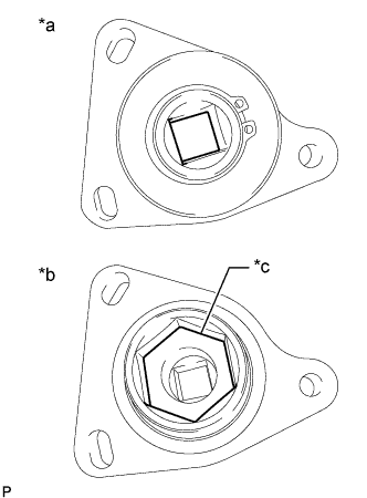
Align the hexagonal portion of SST with the supply pump shaft nut to install SST.
-
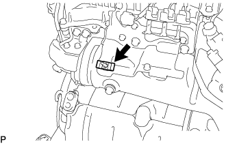
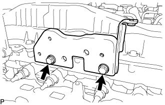
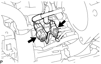
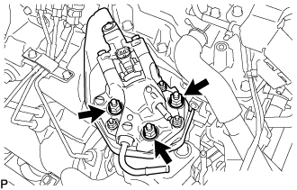
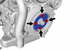
Remove the 2 bolts and No. 1 fuel pump bracket from the cylinder block sub-assembly and supply pump assembly.
-
Loosen the 3 nuts to the ends of the stud bolts.
Note
Do not completely remove the nuts. Otherwise, the supply pump assembly may fall off.
-
Using SST, loosen the supply pump shaft nut and detach the supply pump assembly and injection pump drive gear.
-
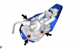
Remove the 3 nuts from the stud bolts.
-
Remove the O-ring from the supply pump assembly.
-
Remove SST from the timing chain cover sub-assembly.
-
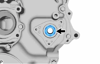
Remove the supply pump shaft nut from the timing chain cover sub-assembly service hole.
-
Remove the crankshaft pulley set bolt and crankshaft pulley from the crankshaft.
-
-
REMOVE INJECTION PUMP INSULATOR
-
Remove the injection pump insulator from the cylinder block sub-assembly.
-
-
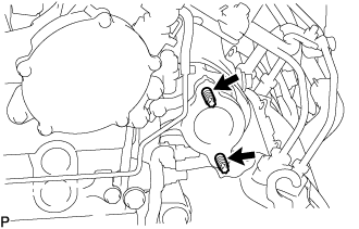
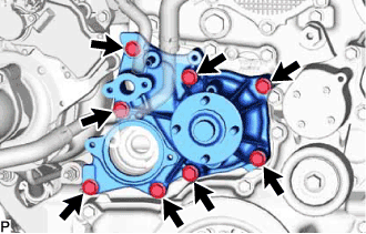
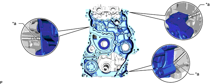
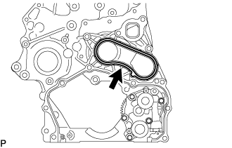
REMOVE TIMING CHAIN COVER SUB-ASSEMBLY
-
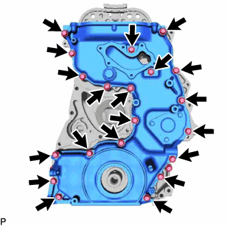
Remove the 20 bolts from the timing chain cover sub-assembly.
-
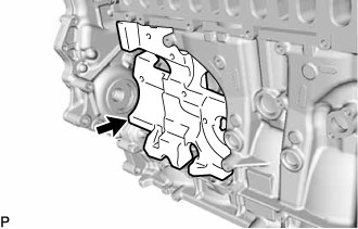
Using a screwdriver wrapped in protective tape, remove the timing chain cover sub-assembly by prying the points in the illustration.
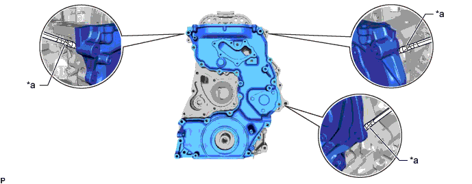
Text in Illustration *a Protective Tape - - Note
Do not damage the contacting surfaces of the timing chain cover sub-assembly and timing chain case assembly.
-
Remove the timing chain case gasket from the timing chain case assembly.
-
-
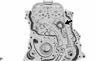
REMOVE FRONT CRANKSHAFT OIL SEAL
-
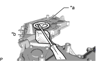
Text in Illustration *a Protective Tape *b Wooden Block Using a screwdriver and wooden block, pull out the front crankshaft oil seal.
Note
Do not damage the surface of the front crankshaft oil seal press fit hole.
-
-
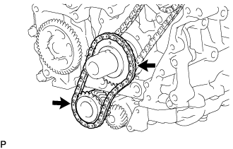
INSPECT BACKLASH OF OIL PUMP GEAR TO OIL PUMP DRIVE GEAR
-
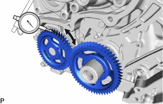
Using a dial indicator, measure the backlash.
Standard gear backlash 0.02 to 0.3 mm (0.000787 to 0.0118 in.) Maximum gear backlash 0.42 mm (0.0165 in.) If the gear backlash is more than the maximum, replace the timing chain case assembly or oil pump drive gear.
-
-
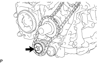
REMOVE OIL PUMP DRIVE GEAR
-
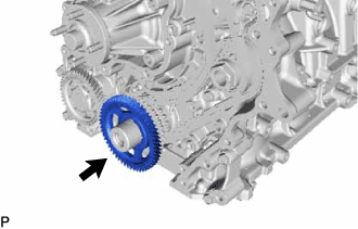
Remove the oil pump drive gear from the crankshaft.
-
-
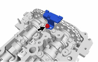
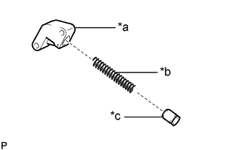
REMOVE NO. 3 CHAIN TENSIONER ASSEMBLY
Note
-
When the pin is removed from the No. 3 chain tensioner assembly, the plunger and 2 springs may come off of the No. 3 chain tensioner assembly body, but this is not a malfunction.
-
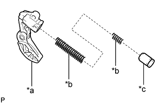
Before installing the plunger and 2 springs to the No. 3 chain tensioner assembly body, check that they are free of foreign matter and not damaged.
-
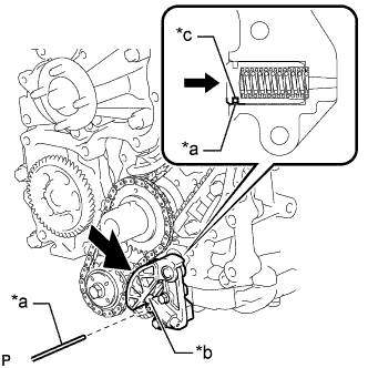
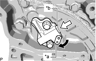
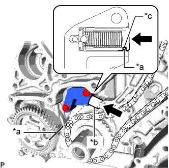
Text in Illustration *a No. 3 Chain Tensioner Assembly Body *b Spring *c Plunger Fully insert the plunger, align the No. 3 chain tensioner assembly body hole with the plunger groove and insert the pin as shown in the illustration.
-
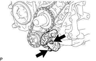
Text in Illustration *a Pin *b Plunger *c Plunger Groove Remove the 2 bolts, No. 3 chain tensioner assembly and gasket from the engine balancer assembly.
-
-
REMOVE NO. 1 BALANCE SHAFT THRUST PLATE
-
Remove the bolt and No. 1 balance shaft thrust plate from the balance shaft gear sub-assembly.
-
-
REMOVE BALANCE SHAFT TIMING SPROCKET, BALANCE SHAFT GEAR SUB-ASSEMBLY AND NO. 3 CHAIN SUB-ASSEMBLY
-
Remove the balance shaft timing sprocket, balance shaft gear sub-assembly with No. 3 chain sub-assembly from the crankshaft and engine balancer assembly.
-
-
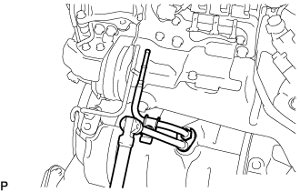
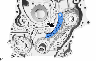
REMOVE TIMING CHAIN GUIDE
-
Remove the bolt and timing chain guide from the cylinder head sub-assembly.
-
-
REMOVE NO. 2 CHAIN TENSIONER ASSEMBLY
-
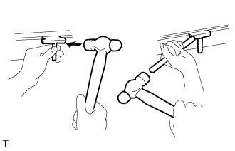
Text in Illustration *a Stopper Plate *b Plunger Allow the plunger to extend slightly, and then rotate the stopper plate clockwise to release the lock. Once the lock is released, push the plunger into the No. 2 chain tensioner assembly.
-
Text in Illustration *a Pin Allow the plunger to extend slightly, and then rotate the stopper plate clockwise to release the lock. Once the lock is released, push the plunger into the No. 2 chain tensioner assembly.
-
Remove the 2 bolts and No. 2 chain tensioner assembly from the timing chain case assembly.
-
-
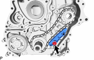
REMOVE NO. 2 CHAIN TENSIONER SLIPPER
-
Remove the bolt and No. 2 chain tensioner slipper from the timing chain case assembly.
-
-
REMOVE NO. 2 CHAIN VIBRATION DAMPER
-
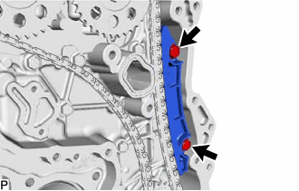
Remove the 2 bolts and No. 2 chain vibration damper from the timing chain case assembly.
-
-
REMOVE NO. 2 CHAIN SUB-ASSEMBLY
-
Remove the No. 2 chain sub-assembly from the camshaft timing sprockets and injection pump drive gear.
-
-
REMOVE NO. 1 CHAIN TENSIONER ASSEMBLY
Note
-
When the pin is removed from the No. 1 chain tensioner assembly, the plunger and spring may come off of the No. 1 chain tensioner assembly body, but this is not a malfunction.
-
Before installing the plunger and spring to the No. 1 chain tensioner assembly body, check that they are free of foreign matter and not damaged.
Text in Illustration *a No. 1 Chain Tensioner Assembly Body *b Spring *c Plunger
-
Text in Illustration *a Pin *b Plunger *c Plunger Groove Fully insert the plunger, align the No. 1 chain tensioner assembly body hole with the plunger groove and insert the pin as shown in the illustration.
-
Remove the 2 bolts, No. 1 chain tensioner assembly and gasket from the cylinder block sub-assembly.
-
-
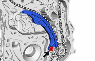
REMOVE NO. 1 CHAIN TENSIONER SLIPPER
-
Remove the No. 1 chain tensioner slipper from the straight pin.
-
-
REMOVE NO. 1 CHAIN VIBRATION DAMPER
-
Remove the bolt and No. 1 chain vibration damper from the cylinder block sub-assembly.
-
-
REMOVE CRANKSHAFT TIMING SPROCKET, INJECTION PUMP DRIVE GEAR WITH NO. 1 CHAIN SUB-ASSEMBLY
-
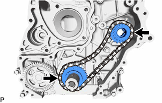
Remove the crankshaft timing sprocket, injection pump drive gear with No. 1 chain sub-assembly from the crankshaft and supply pump shaft.
-
-
REMOVE CAMSHAFT TIMING SPROCKET
-
for Exhaust Side:
-
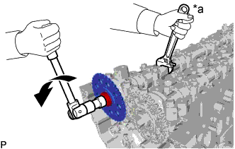
Text in Illustration *a Hold Turn Hold the hexagonal portion of the No. 2 camshaft with a wrench and remove the camshaft timing sprocket bolt and camshaft timing sprocket from the No. 2 camshaft.
Note
Be careful not to damage the No. 2 camshaft or cylinder head sub-assembly with the wrench.
-
-
for Intake Side:
-
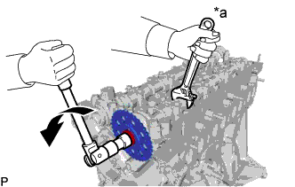
Text in Illustration *a Hold Turn Hold the hexagonal portion of the camshaft with a wrench and remove the camshaft timing sprocket bolt and camshaft timing sprocket from the camshaft.
Note
Be careful not to damage the camshaft or cylinder head sub-assembly with the wrench.
-
-
-
REMOVE TIMING CHAIN CASE ASSEMBLY
-
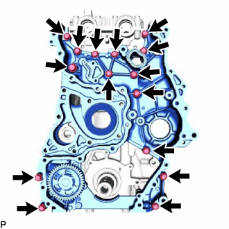
Remove the 15 bolts from the timing chain case assembly.
-
Using a screwdriver wrapped in protective tape, remove the timing chain case assembly by prying the points in the illustration.
Text in Illustration *a Protective Tape - - Note
Do not damage the contacting surfaces of the timing chain case assembly, cylinder head sub-assembly and cylinder block sub-assembly.
-
Remove the 4 O-rings from the cylinder head sub-assembly and cylinder block sub-assembly.
-
Remove the No. 2 water pump gasket from the timing chain case assembly.
-