RADIATOR INSTALLATION

-
INSTALL WATER BY-PASS PIPE SUB-ASSEMBLY
-
Install the water by-pass pipe sub-assembly to the radiator assembly, and slide the clamp to secure the hose.
-
-
INSTALL OIL COOLER HOSE
-
Install the 2 oil cooler hoses to the radiator assembly, and slide the 2 clamps to secure the hoses.
-
-
INSTALL RADIATOR ASSEMBLY
-
Install the 4 grommets to the radiator assembly.
-
Install the radiator assembly to the vehicle.
Note
Do not drop the radiator assembly.
-
Connect the No. 2 radiator hose and No. 3 radiator hose to the radiator assembly, and slide the 2 hose clamps to secure the hoses.
-
-
INSTALL NO. 2 FAN SHROUD
-
Install the No. 2 fan shroud with the 2 bolts.
- Torque:
- 13 N*m { 127 kgf*cm, 9 ft.*lbf }
Note
-
Do not drop the radiator assembly.
-
Do not damage the radiator assembly when installing the No. 2 fan shroud.
-
Connect the water by-pass pipe sub-assembly to the radiator assembly with the bolt.
- Torque:
- 13 N*m { 127 kgf*cm, 9 ft.*lbf }
-
Connect the No. 2 water by-pass hose to the water by-pass pipe sub-assembly, and slide the hose clamp to secure the hose.
-
-
INSTALL FAN SHROUD
-
Install the fan shroud to the No. 2 fan shroud with the 6 bolts.
- Torque:
- 7.1 N*m { 72 kgf*cm, 63 in.*lbf }
Note
Do not drop the radiator assembly.
-
Attach the 2 clamps and connect the 2 connectors.
-
-
INSTALL FAN BRACKET SUB-ASSEMBLY
-
Install the fan bracket sub-assembly with the 2 bolts and 2 nuts.
- Torque:
- 20 N*m { 199 kgf*cm, 14 ft.*lbf }
-
Attach the clamp.
-
-
CONNECT OIL COOLER HOSE
-
Connect the 2 oil cooler hoses to the 2 oil cooler tubes, and slide the 2 hose clamps to secure the hoses.
-
Attach the 2 clamps and connect the oil cooler hose to the fan shroud.
-
-
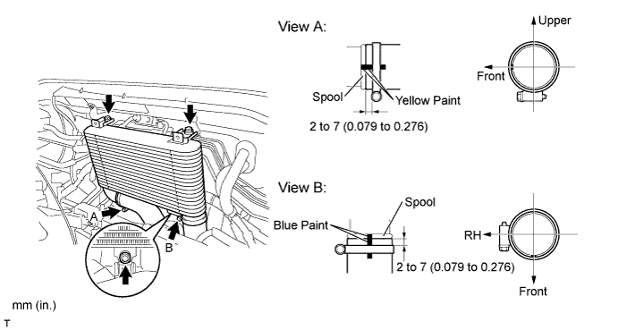
INSTALL INTERCOOLER ASSEMBLY
-
Temporarily install the intercooler with the 3 bolts.
-
Connect the No. 3 air hose and tighten the hose clamp as shown in the illustration.
- Torque:
- 6.0 N*m { 61 kgf*cm, 53 in.*lbf }
Note
-
Insert the hose until it is flush with the pipe spool end, install the clip and then check that it is securely connected.
-
Check that the hose does not interfere with any other parts.
-
Check that the hose is not twisted.
-
Connect the No. 2 air hose and tighten the hose clamp as shown in the illustration.
- Torque:
- 6.0 N*m { 61 kgf*cm, 53 in.*lbf }
Note
-
Insert the hose until it is flush with the pipe spool end, install the clip and then check that it is securely connected.
-
Check that the hose does not interfere with any other parts.
-
Check that the hose is not twisted.
-
Tighten the 3 bolts.
- Torque:
- 18 N*m { 178 kgf*cm, 13 ft.*lbf }
-
-
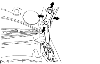
INSTALL UPPER RADIATOR SUPPORT SUB-ASSEMBLY
-
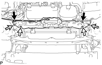
Install the upper radiator support sub-assembly with the 4 bolts and 2 screws.
- Torque:
- for bolt A
- 13 N*m { 127 kgf*cm, 9 ft.*lbf }
- for bolt B
- 5.5 N*m { 56 kgf*cm, 49 in.*lbf }
Text in Illustration 
Bolt A 
Bolt B 
Screw -
Attach the 2 clamps to connect the hood lock control cable assembly to the upper radiator support sub-assembly.
-
Connect the water by-pass hose to the radiator assembly, and slide the hose clamp to secure the hose.
-
-
INSTALL HOOD LOCK ASSEMBLY
-
Connect the hood lock control cable assembly to the hood lock assembly.
-
Install the hood lock assembly with the 3 bolts.
- Torque:
- 12 N*m { 122 kgf*cm, 9 ft.*lbf }
-
-
CONNECT UREA TANK FILLER PIPE ASSEMBLY
-
Connect the urea tank filler pipe support to the upper radiator support sub-assembly with the 2 bolts.
- Torque:
- 7.5 N*m { 76 kgf*cm, 66 in.*lbf }
-
-
INSTALL WINDSHIELD WASHER MOTOR AND PUMP ASSEMBLY
-
Connect the 2 connectors and 2 washer hoses.
-
Attach the hose clamp.
-
Install the windshield washer motor and pump assembly with the 2 bolts.
- Torque:
- 4.9 N*m { 50 kgf*cm, 43 in.*lbf }
-
-
ADD WINDSHIELD WASHER FLUID
-
INSTALL RADIATOR RESERVE TANK ASSEMBLY
-
Install the radiator reservoir assembly with the bolt.
- Torque:
- 8.0 N*m { 82 kgf*cm, 71 in.*lbf }
-
Connect the No. 2 water by-pass hose to the radiator reserve tank assembly, and slide the hose clamp to secure the hose.
-
Connect the water by-pass hose to the radiator reserve tank assembly, and slide the clamp to secure the hose.
-
-
INSTALL NO. 1 AIR INLET DUCT
-
Install the No. 1 air inlet duct and No. 2 air inlet duct with the 2 bolts and 5 clips.
- Torque:
- 7.0 N*m { 71 kgf*cm, 62 in.*lbf }
-
-
INSTALL W/RECEIVER CONDENSER ASSEMBLY
-
INSTALL HOOD LOCK SUPPORT BRACE SUB-ASSEMBLY
-
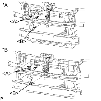
Text in Illustration *A for Standard Body *B for Wide Body Install the hood lock support brace sub-assembly with the 3 bolts.
- Torque:
- for bolt A
- 5.5 N*m { 56 kgf*cm, 49 in.*lbf }
- for bolt B
- 12 N*m { 122 kgf*cm, 9 ft.*lbf }
-
-
INSTALL FRONT BUMPER REINFORCEMENT
-
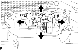
ADJUST HOOD SUB-ASSEMBLY
-
Loosen the bolts to adjust the hood front and back, side to side.
- Torque:
- 13 N*m { 133 kgf*cm, 10 ft.*lbf }
Note
Perform this procedure after replacement of the centering bolts with the supplied ones.
-
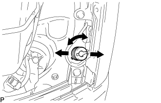
Turn the cushion to adjust the hood gap.
-
Loosen the hood lock to adjust the hood front up and down, side to side.
- Torque:
- 12 N*m { 122 kgf*cm, 9.0 ft.*lbf }
Note
Perform this procedure after replacement of the centering bolts with the supplied ones.
-
-
ADD ENGINE COOLANT
-
Firmly tighten the drain plugs.
-
Fill the radiator reserve tank assembly with engine coolant to the top of the inlet.
Standard capacity 13.9 liters (14.6 US qts, 12.2 Imp qts) Note
Do not substitute plain water for engine coolant.
Tech Tips
-
Use of improper coolants may damage the engine cooling system.
-
Use only TOYOTA Super Long Life Coolant (SLLC) or similar high quality ethylene glycol based non-silicate, non-amine, non-nitrite, and non-borate coolant with long-life hybrid organic acid technology (coolant with long-life hybrid organic acid technology consists of a combination of low phosphates and organic acids).
-
-
Loosen the bleeder plug of the water outlet sub-assembly.
-
When air is bled and the engine coolant drains out, firmly tighten the bleeder plug.
- Torque:
- 8.0 N*m { 82 kgf*cm, 71 in.*lbf }
-
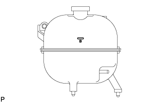
Add engine coolant up to the B line mark in the radiator reserve tank assembly and install the radiator cap sub-assembly.
-
Warm up the engine until the thermostat opens.
-
While the thermostat is open, circulate the engine coolant for several minutes.
Tech Tips
The thermostat open timing can be confirmed by pressing the No. 3 radiator hose by hand, and checking when the engine coolant starts to flow inside the hose.
-
-
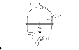
After the engine cools down, check that the engine coolant level is between the LOW and FULL line.
-
-
INSPECT FOR COOLANT LEAK
CAUTION:
Do not remove the radiator cap sub-assembly while the engine assembly and radiator assembly are still hot. Hot, pressurized engine coolant and steam may be released and cause serious burns.
-
Fill the radiator assembly with coolant and attach a radiator cap tester to the radiator.
-
Warm up the engine.
-
Using a radiator cap tester, increase the pressure inside the radiator assembly to 137 kPa (1.4 kgf/cm2, 19.9 psi), and check that the pressure does not drop.
Tech Tips
If the pressure drops, check the hoses, radiator assembly and engine water pump assembly for leaks. If no external leaks are found, check the heater core, cylinder block sub-assembly and cylinder head sub-assembly.
-
-
INSPECT AUTOMATIC TRANSMISSION FLUID LEVEL
-
INSPECT FOR FLUID LEAK
CAUTION:
Use caution while the engine is idling and the radiator fan is operating.
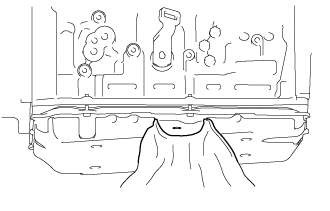
Note
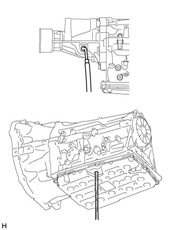
When removing the overflow plug, automatic transmission fluid may enter through the gap in the automatic transmission oil pan sub-assembly. Therefore, insert cloth between the gap in the automatic transmission oil pan sub-assembly as shown in the illustration to prevent the entry of automatic transmission fluid.
-
Lift the vehicle.
Note
Set the vehicle on a lift so that the vehicle is kept level when it is lifted up (make sure that the tilt angle from the front to rear of the vehicle is within +/-1°).
-
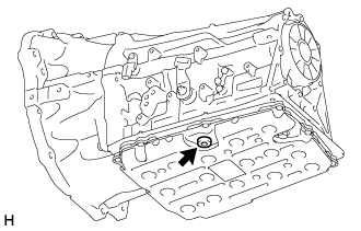
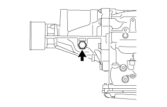
Using a 5 mm hexagon socket wrench, remove the overflow plug and gasket from the automatic transmission assembly.
CAUTION:
Be careful as the automatic transmission fluid coming out of the overflow hole is hot.
-
Check the amount of automatic transmission fluid that comes out of the overflow hole.
-
If the amount of automatic transmission fluid that comes out of the overflow hole is large, proceed to step [*1].
-
If no automatic transmission fluid comes out of the overflow hole, proceed to step [*2].
Note
If only a small amount of automatic transmission fluid (approximately 5 cc) comes out of the overflow hole, then only automatic transmission fluid remaining in the overflow tube of overflow hole has come out. This is not considered to be overflow.
-
-
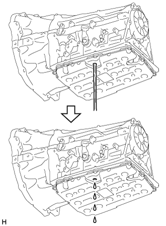
If the amount of automatic transmission fluid that comes out of the overflow hole is large, wait until the automatic transmission fluid flow slows and only drips come out. [*1]
Tech Tips
The automatic transmission fluid flow will not stop completely because the automatic transmission fluid continues to expand as its temperature increases.
-
If no automatic transmission fluid comes out of the overflow hole, remove the refill plug and O-ring. Then add automatic transmission fluid to the refill hole until it flows out of the overflow hole. Wait until the automatic transmission fluid flow slows and only drips come out. [*2]
Note
-
Use Toyota Genuine ATF WS.
-
Be sure to add automatic transmission fluid slowly. If automatic transmission fluid is added quickly, the automatic transmission fluid may hit internal parts and bounce back, resulting in automatic transmission fluid coming out of the refill hole.
-
-
Wait until the automatic transmission fluid flow slows and only drips come out.
Tech Tips
The automatic transmission fluid flow will not stop completely because the automatic transmission fluid continues to expand as its temperature increases.
-
Using a 5 mm hexagon socket wrench, install a new gasket and the overflow plug to the automatic transmission assembly.
- Torque:
- 20 N*m { 204 kgf*cm, 15 ft.*lbf }
-
Install a new O-ring and the refill plug to the automatic transmission assembly.
- Torque:
- 39 N*m { 400 kgf*cm, 29 ft.*lbf }
-
Lower the vehicle.
-
Turn the ignition switch off.
Tech Tips
Turning the ignition switch off exits automatic transmission fluid temperature detection mode.
-
Disconnect the GTS from the DLC3 (when using the GTS).
-
-
CHARGE WITH REFRIGERANT
-
Perform vacuum purging using a vacuum pump.
-
Charge with refrigerant HFC-134a (R134a).
Standard Single A/C 520 to 580g (18.3 to 20.5 oz.) Dual A/C 670 to 730g (23.0 to 25.7 oz.) - SST
- 07110-58060 ( 07117-58090, 07117-78050, 07117-58070, 07117-58060, 07117-58080, 07117-88060, 07117-88070, 07117-88080 )
Note
-
Do not operate the cooler compressor before charging refrigerant as the cooler compressor does not work properly without any refrigerant, which causes the compressor to overheat.
-
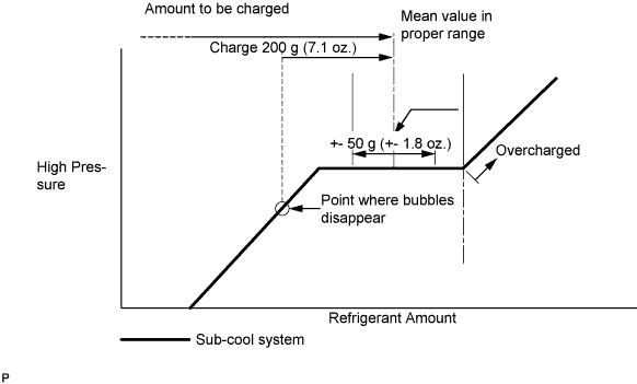
Approximately 100 g (3.5 oz.) of refrigerant may need to be charged after bubbles disappear. The refrigerant amount should be checked by quantity, and not with the sight glass.
Tech Tips
Prepare a service can to recharge refrigerant if using the refrigerant gas collected with the freon collection/recycling device because the collective rate of the device is approximately 90%.
-
-
INSPECT FOR REFRIGERANT LEAK
-
After recharging refrigerant gas, check for leakage of refrigerant gas using a halogen leak detector.
-
Carry out the test under the following conditions:
-
Stop the engine.
-
Secure good ventilation (the gas leak detector may react to volatile gases which are not refrigerant, such as evaporated gasoline and exhaust gas).
-
Repeat the test 2 or 3 times.
-
Make sure that there is some refrigerant remaining in the refrigeration system.
When the compressor is off: approx. 392 to 588 kPa (4 to 6 kgf/cm2, 57 to 85 psi)
-
-
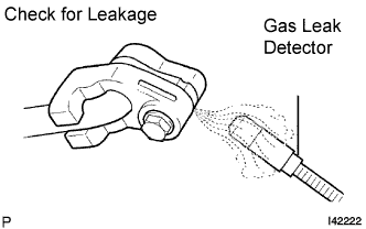
Using a gas leak detector, check for leakage of the refrigerant line.
-
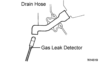
Bring the gas leak detector close to the drain hose with the detector's power off.
Tech Tips
-
After the blower motor has stopped, let the cooling unit stand for more than 15 minutes.
-
Bring the gas leak detector sensor under the drain hose.
-
When bringing the gas leak detector close to the drain hose, make sure that the gas leak detector does not react to volatile gases.
If such reaction is unavoidable, the vehicle must be lifted up.
-
-
If a gas leak is not detected on the drain hose, remove the blower motor control from the cooling unit. Insert the gas leak detector sensor into the unit and perform the test.
-
Disconnect the pressure switch connector and leave it for approximately 20 minutes. Bring the gas leak detector close to the pressure switch and perform the test.
-