EXHAUST PIPE INSTALLATION

-
INSTALL FRONT EXHAUST PIPE ASSEMBLY
-
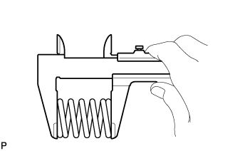
Using a vernier caliper, measure the free length of the compression spring.
Minimum free length 38.5 mm (1.52 in.)
-
If the free length is less than the minimum, replace the compression spring.
-
-
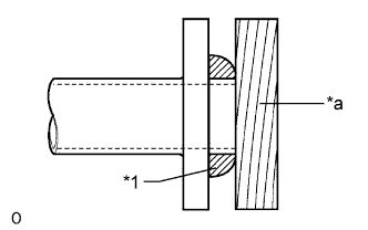
Text in Illustration *1 Gasket *a Wooden Block Using a plastic-faced hammer and wooden block, tap in a new gasket until its surface is flush with the front exhaust pipe assembly.
Note
-
Be sure to install the gasket so that it faces the correct direction.
-
Do not reuse the gasket.
-
Do not damage the gasket.
-
When connecting the front exhaust pipe assembly, do not push in the gasket with the front exhaust pipe assembly.
-
-
Connect the front exhaust pipe assembly to the 2 exhaust pipe supports.
-
Install a new gasket and the front exhaust pipe assembly and 2 compression springs with the 2 bolts.
- Torque:
- 43 N*m { 438 kgf*cm, 32 ft.*lbf }
-
-
INSTALL UREA INJECTOR SET
-
INSTALL CENTER EXHAUST PIPE ASSEMBLY
-
Install a new gasket to the center exhaust pipe assembly.
-
Connect the center exhaust pipe assembly to the 2 exhaust pipe supports.
-
Install the center exhaust pipe assembly with the 2 bolts and 2 new nuts.
- Torque:
- 48 N*m { 489 kgf*cm, 35 ft.*lbf }
-
-
INSTALL NITROGEN OXIDES SENSOR
-
Temporarily install the nitrogen oxides sensor.
-
Install the controller portion with the 2 nuts, and then attach the connector and clamp.
- Torque:
- 8.0 N*m { 82 kgf*cm, 71 in.*lbf }
-
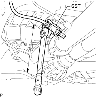
Text in Illustration *a Torque Wrench Fulcrum Length Using SST, install the nitrogen oxides sensor.
- SST
- 09224-00012
- Torque:
- Specified tightening torque
- 55 N*m { 561 kgf*cm, 41 ft.*lbf }
Note
-
Replace with a new part if it is dropped or if it receives a strong impact.
-
Complete the installation so that there is no tension or slack in the harness of the nitrogen oxides sensor, and there is no interference.
Tech Tips
-
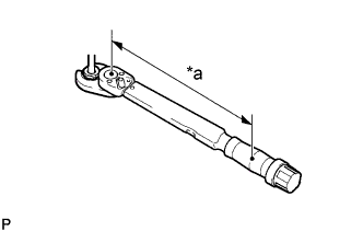
Calculate the torque wrench reading when changing the fulcrum length of the torque wrench Click here.
-
When using SST (fulcrum length of 30 mm (1.181 in.)) + torque wrench (fulcrum length of 255 mm (10.039 in.)): 49 N*m (502 kgf*cm, 36 ft.*lbf)
-
-
INSTALL NO. 4 EXHAUST GAS TEMPERATURE SENSOR
-
Text in Illustration *a Torque Wrench Fulcrum Length Using a 14 mm union nut wrench, install the No. 4 exhaust gas temperature sensor to the front exhaust pipe assembly.
Torque Specified tightening torque 30 N*m {306 kgf*cm, 22 ft.*lbf} Note
If the No. 4 exhaust gas temperature sensor is dropped, replace it with a new.
Tech Tips
-
Calculate the torque wrench reading when changing the fulcrum length of the torque wrench Click here.
-
When using a union nut wrench (fulcrum length of 25 mm (0.984 in.)) + torque wrench (fulcrum length of 180 mm (7.09 in.)): 26 N*m (268 kgf*cm, 19 ft.*lbf)
-
-
Connect the connector to the No. 4 exhaust gas temperature sensor.
-
-
INSTALL NO. 1 FRONT FLOOR HEAT INSULATOR
-
Install the No. 1 front floor heat insulator with the 3 bolts.
- Torque:
- 17 N*m { 168 kgf*cm, 12 ft.*lbf }
-
-
INSTALL EXHAUST PIPE DAMPER
-
Install the exhaust pipe damper with the 2 bolts.
- Torque:
- 19 N*m { 194 kgf*cm, 14 ft.*lbf }
-
-
INSTALL TAILPIPE ASSEMBLY
-
Install a new gasket to the tailpipe assembly.
-
Connect the tailpipe assembly to the exhaust pipe support.
-
Connect the tailpipe assembly to the center exhaust pipe assembly.
-
Install the 2 bolts.
- Torque:
- 48 N*m { 489 kgf*cm, 35 ft.*lbf }
-
-
INSPECT FOR EXHAUST GAS LEAK
-
If gas is leaking, tighten the areas necessary to stop the leak. Replace damaged parts as necessary.
-