EXHAUST PIPE (w/ DPF) INSTALLATION

-
INSTALL CATALYTIC CONVERTER BRACKET SUB-ASSEMBLY
-
Install the catalytic converter bracket with the bolt.
- Torque:
- 18 N*m { 184 kgf*cm, 13 ft.*lbf }
-
-
INSTALL NO. 2 EXHAUST PIPE PROTECTOR
-
Install the No. 2 exhaust pipe protector with the 2 bolts.
- Torque:
- 11 N*m { 107 kgf*cm, 8 ft.*lbf }
-
-
INSTALL NO. 1 EXHAUST PIPE PROTECTOR
-
Install the No. 1 exhaust pipe protector with the 3 bolts.
- Torque:
- 11 N*m { 107 kgf*cm, 8 ft.*lbf }
-
-
INSTALL NO. 3 EXHAUST GAS TEMPERATURE SENSOR
Note
If the sensor is dropped, replace it with a new one.
-
Using a 14 mm union nut wrench, install the No. 3 exhaust gas temperature sensor.
- Torque:
- 30 N*m { 306 kgf*cm, 22 ft.*lbf }
Tech Tips
-
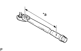
Calculate the torque wrench reading when changing the fulcrum length of the torque wrench.
Text in Illustration *a Torque Wrench Fulcrum Length -
When using a union nut wrench (fulcrum length of 25 mm (0.984 in.)) + torque wrench (fulcrum length of 180 mm (7.087 in.)): 26 N*m (268 kgf*cm, 19 ft.*lbf)
-
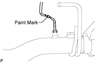
The sensor has 3 paint marks as shown in the illustration.
-
-
INSTALL NO. 2 EXHAUST GAS TEMPERATURE SENSOR
Note
If the sensor is dropped, replace it with a new one.
-
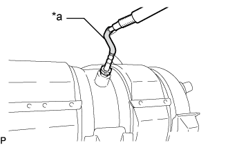
Text in Illustration *a Wire Harness Tube Color
(Orange)
Using a 14 mm union nut wrench, install the No. 2 exhaust gas temperature sensor.
- Torque:
- 30 N*m { 306 kgf*cm, 22 ft.*lbf }
-
-
INSTALL EXHAUST GAS TEMPERATURE SENSOR
Note
If the sensor is dropped, replace it with a new one.
-
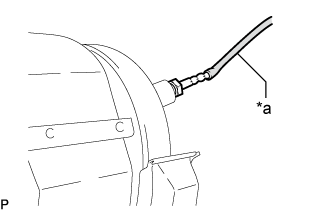
Text in Illustration *a Wire Harness Tube Color
(Yellow)
Using a 14 mm union nut wrench, install the exhaust gas temperature sensor.
- Torque:
- 30 N*m { 306 kgf*cm, 22 ft.*lbf }
-
-
INSTALL FRONT EXHAUST PIPE ASSEMBLY
-
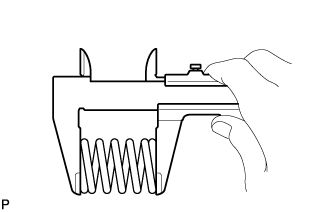
Using a vernier caliper, measure the free length of the compression spring.
Minimum free length 40.5 mm (1.59 in.)
-
If the free length is less than the minimum, replace the compression spring.
-
-
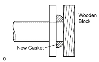
Using a plastic-faced hammer and wooden block, tap on a new gasket until its surface is flush with the front exhaust pipe.
Note
-
Be sure to install the gasket so that it faces the correct direction.
-
Do not reuse the gasket.
-
Do not damage the gasket.
-
When connecting the exhaust pipe, do not push in the gasket with the exhaust pipe.
-
-
Install a new gasket and the front exhaust pipe to the catalytic converter with pipe with 3 new nuts.
- Torque:
- 63 N*m { 642 kgf*cm, 46 ft.*lbf }
-
Connect the front exhaust pipe to the 2 exhaust pipe supports.
-
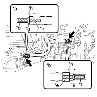
Text in Illustration *a No. 1 Exhaust Pipe Air Hose Side *b No. 7 Exhaust Pipe Air Hose Side *c No. 1 Exhaust Pipe Air Hose Paint Mark (Green) *d front exhaust pipe Assembly Marking (Green) *e No. 7 Exhaust Pipe Air Hose Paint Mark (Pink) *f front exhaust pipe Assembly Marking (Pink) *g Stopper *h 4 to 10 mm Connect the No. 1 exhaust pipe air hose and No. 7 exhaust pipe air hose to the front exhaust pipe with 2 new clips.
Note
-
Align the paint marks of the front exhaust pipe and exhaust pipe air hose and push on the exhaust pipe air hose until it contacts the stopper.
-
Make sure the clip is 4 to 10 mm (0.157 to 0.394 in.) from the end of the exhaust pipe air hose when installing the clip.
-
Make sure that there is no slack in the exhaust pipe air hose, and that it is not twisted or bent.
-
Take care not to damage the inner or outer surface of the exhaust pipe air hose when installing it. If the exhaust pipe air hose is damaged, replace it with a new one.
-
-
Connect the No. 3 exhaust gas temperature sensor connector and attach the 2 clamps.
-
Connect the No. 2 exhaust gas temperature sensor connector and attach the 2 clamps.
-
Connect the exhaust gas temperature sensor connector and attach the clamp.
-
-
INSTALL AIR FUEL RATIO SENSOR
-
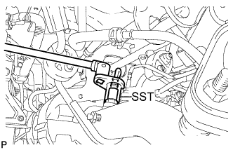
Using SST, install the air fuel ratio sensor to the front exhaust pipe.
- SST
- 09224-00010
- Torque:
- without SST
- 44 N*m { 449 kgf*cm, 32 ft.*lbf }
- with SST
- 39 N*m { 402 kgf*cm, 29 ft.*lbf }
Tech Tips
-
Use a torque wrench with a fulcrum length of 30 cm (11.8 in.). When using a torque wrench with a fulcrum length that is not 30 cm (11.8 in.), calculate the torque specification for the torque wrench and SST based on the "without SST" torque specification Click here.
-
Make sure SST and the wrench are connected in a straight line.
-
Connect the air fuel ratio sensor connector and attach the clamp.
-
-
INSTALL AIR TUBE COVER
-
Attach the 2 clips and clamp.
-
Install the air tube cover with the 2 bolts.
- Torque:
- 20 N*m { 199 kgf*cm, 14 ft.*lbf }
-
-
INSTALL CENTER EXHAUST PIPE ASSEMBLY
-
except Super Long Wheelbase:
Install the center exhaust pipe to the 3 exhaust pipe supports.
-
for Super Long Wheelbase, for Type A:
Install the center exhaust pipe to the 3 exhaust pipe supports.
-
for Super Long Wheelbase, for Type B:
Install the center exhaust pipe to the 4 exhaust pipe supports.
-
Install the center exhaust pipe and 2 compression springs with the 2 bolts.
- Torque:
- 43 N*m { 438 kgf*cm, 32 ft.*lbf }
-
-
INSTALL EXHAUST TAILPIPE ASSEMBLY
-
Install the tailpipe to the exhaust pipe support.
-
Install a new gasket and connect the tailpipe to the center exhaust pipe with the 2 bolts. Alternately tighten the bolts in several passes.
- Torque:
- 48 N*m { 489 kgf*cm, 35 ft.*lbf }
Note
Do not reuse the gasket.
-
-
INSPECT FOR EXHAUST GAS LEAK
-
If gas is leaking, tighten the areas necessary to stop the leak. Replace damaged parts as necessary.
-
-
PERFORM CATALYST RECORD OF DPF THERMAL DETERIORATION CLEAR