UREA TANK INSTALLATION

-
INSTALL UREA PUMP
-
Install a new gasket to the urea tank sub-assembly.
-
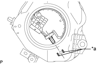
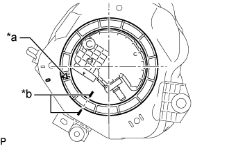
Text in Illustration *a Matchmark Install the urea pump to the urea tank sub-assembly as shown in the illustration.
-
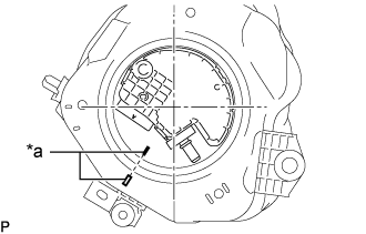
Text in Illustration *a Co-rotation Prevention Check Mark Apply a co-rotation prevention check mark to the urea pump and urea tank sub-assembly.
Tech Tips
Perform this procedure when replacement of the urea pump is necessary.
-
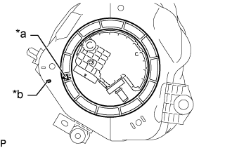
Text in Illustration *a Rotational Start Point Mark
(Urea Pump Gauge Retainer Side)
*b Rotational Start Point Mark
(Urea Tank Sub-assembly Side)
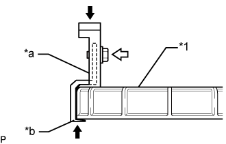
Temporarily place the urea pump gauge retainer by aligning the rotational start point mark of the urea urea pump gauge retainer with the rotational start point mark of the urea tank sub-assembly while pressing the urea pump into the urea tank assembly.
-
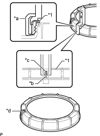
Text in Illustration *1 Urea Pump Gauge Retainer *a SST (Claw Set) *b Rib *c Cutout *d SST (Claw Set) Incorrect Installation Point (Rotational Start Point Mark of Urea pump Gauge Retainer) Set 4 SSTs (claw sets) to the urea pump gauge retainer and temporarily install.
- SST
- 09808-14031 ( 09808-01080, 09808-01090, 09808-01100 )
-
Text in Illustration *1 Urea Pump Gauge Retainer *a SST (Claw Set) *b Press 
Pinch 
SST (Bolt) While firmly pressing the claw of SST into rib of the urea pump gauge retainer, tighten the bolt.
-
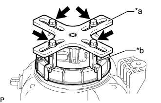
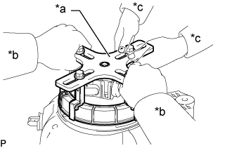
Text in Illustration *a SST (Plate) *b SST (Claw Set) SST (Bolt) Temporarily install SST (plate) to SST (claw set) with 4 SSTs (bolts).
-
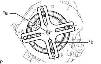
Text in Illustration *a Center of Urea Pump Gauge Retainer *b SST (Plate) Adjust the position of SST (plate) so that the setting hole of SST (handle) aligns with the center of the urea pump gauge retainer.
-
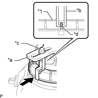
Text in Illustration *1 Urea Pump Gauge Retainer *a SST (Plate) *b SST (Claw Set) *c SST (Bolt) *d Rib Press While firmly pressing SST (claw set) into rib of the urea pump gauge retainer, tighten SST (bolt).
-
Text in Illustration *a Tighten Start Position *b Co-rotation Prevention Check Mark While one person presses the urea pump into the urea tank sub-assembly, have another person firmly press the urea pump gauge retainer into the threads of the urea tank assembly and tighten approximately one and a half turns.
Note
-
Do not any tools other than SST, such as a screwdriver, etc.
-
Do not excessive force when pressing down on SST, as the urea pump will place excessive force on urea pump gauge retainer and be difficult to remove, and parts may be damaged.
-
Do not use an impact wrench or turn SST handle with excessive force, as parts may be damaged.
-
Do not rotate the urea pump gauge retainer when the co-rotation prevention check mark is out of place.
-
-
Text in Illustration *a SST (Plate) *b Person in Change of Tightening *c Person in Charge of Supporting While one person presses the urea pump into the urea tank sub-assembly have another person slowly tighten approximately half turns.
-
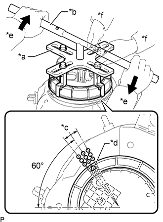
Text in Illustration *a SST (Plate) *b SST (Handle) *c Tightening Complete Position *d Rotational Start Point Mark of Urea Pump Gauge Retainer *e Person in Charge of Tightening *f Person in Charge of Supporting Tighten Install SST (handle) to SST (plate).
- SST
- 09808-14031 ( 09808-01010, 09808-01020 )
-
While one person presses the urea pump onto the urea tank sub-assembly, have another person use SST (handle) and slowly tighten the urea pump gauge retainer until it reaches the tightening complete position.
-
-
INSTALL UREA TANK SUB-ASSEMBLY
-
Install the clip to the urea tank sub-assembly.
-
Install the urea tank sub-assembly to the body with the 3 bolts and clip.
- Torque:
- 14 N*m { 146 kgf*cm, 11 ft.*lbf }
-
-
CONNECT UREA TUBE WITH HEATER ASSEMBLY
Note
Check for dirt or mud on the urea pump and around the urea tube connector before connection. Clean if necessary.
-
Connect the urea tube with heater assembly to the urea pump.
Tech Tips
If there is any solidified urea solution (white solids) on the connection areas of the urea tube with heater assembly and urea pump, clean the solids off with water. Otherwise, they may prevent the O-ring from sealing properly.
-
Wash the connection area of the urea tube connector with water to remove all solidified urea solution (white solids).
-
Wipe off the connection area of the urea pump with water to remove all solidified urea solution (white solids).
-
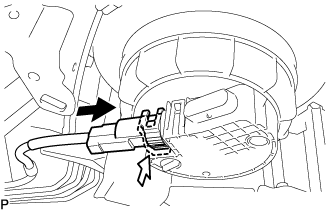
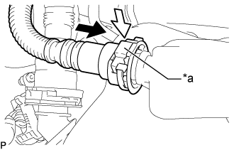
Align the axis of the urea tube connector with the axis of the urea pump. Push the urea tube connector into the urea pump until the urea tube connector makes a "click" sound.
Text in Illustration Push Push Down -
After connecting the urea pump and the urea tube connector, check that the urea pump and urea tube connector are securely connected by trying to pull them apart.
-
-
Attach the lock claws to the urea tube connector by pushing down on the cover.
-
Attach the clamp and connect the No. 1 urea tube with heater to the urea tank sub-assembly.
-
-
CONNECT UREA TANK FILLER PIPE ASSEMBLY
-
Connect the urea tank filler tube of the urea tank filler pipe assembly to the urea tank sub-assembly.
Note
Check for dirt or mud on the urea tank sub-assembly and around the urea tank filler tube connector before connection. Clean if necessary.
Tech Tips
If there is any solidified urea solution (white solids) on the connection areas of the urea tank filler tube and urea tank sub-assembly, clean the solids off with water. Otherwise, they may prevent the O-ring from sealing properly.
-
Wash the connection area of the urea tank filler tube connector with water to remove all solidified urea solution (white solids).
-
Wipe off the connection area of the urea tank sub-assembly with water to remove all solidified urea solution (white solids).
-

Text in Illustration *a Retainer Push Push Down Align the axis of the urea tank filler tube connector with the axis of the urea tank sub-assembly. Push the urea tank filler tube connector into the urea tank sub-assembly until the urea tank filler tube connector makes a "click" sound.
-
Push down the retainer.
-
After connecting the urea tank sub-assembly and the urea tank filler tube connector, check that the urea tank sub-assembly and urea tank filler tube connector are securely connected by trying to pull them apart.
-
-
Connect the urea tank breather tube of the urea tank filler pipe assembly to the urea tank sub-assembly.
Note
Check for dirt or mud on the urea tank sub-assembly and around the urea tank breather tube connector before connection. Clean if necessary.
Tech Tips
If there is any solidified urea solution (white solids) on the connection areas of the urea tank breather tube and urea tank sub-assembly, clean the solids off with water. Otherwise, they may prevent the O-ring from sealing properly.
-
Wash the connection area of the urea tank breather tube connector with water to remove all solidified urea solution (white solids).
-
Wipe off the connection area of the urea tank sub-assembly with water to remove all solidified urea solution (white solids).
-
Text in Illustration *a Retainer Push Push Down Align the axis of the urea tank breather tube connector with the axis of the urea tank sub-assembly. Push the urea tank breather tube connector into the urea tank sub-assembly until the urea tank breather tube connector makes a "click" sound.
-
Push down the retainer.
-
After connecting the urea tank sub-assembly and the urea tank breather tube connector, check that the urea tank sub-assembly and urea tank breather tube connector are securely connected by trying to pull them apart.
-
-
-
CONNECT WIRE HARNESS
-
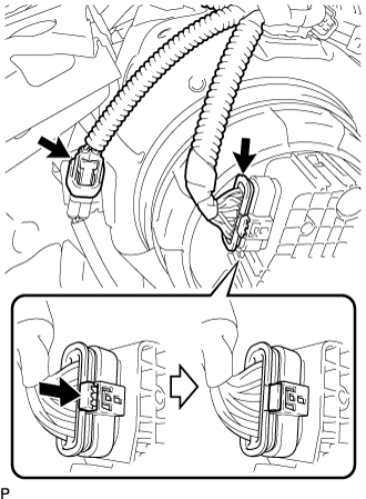
Attach the 2 clamps and connect the front side wiring sub-assembly to the urea tank sub-assembly.
-
Connect the 2 connectors to the front side wiring sub-assembly.
-
Connect the connector to the urea pump as shown in the illustration.
-
Connect the connector to the urea tube with heater assembly.
-
-
INSTALL UREA TANK PROTECTOR
-
Install the urea tank protector to the body with the 3 bolts.
- Torque:
- 20 N*m { 204 kgf*cm, 15 ft.*lbf }
-
-
INSTALL FRONT BUMPER COVER