EGR VALVE REMOVAL
-
DRAIN ENGINE COOLANT
CAUTION:
Do not remove the radiator cap sub-assembly while the engine assembly and radiator assembly are still hot. Pressurized, hot engine coolant and steam may be released and cause serious burns.
-
Connect a hose with an inside diameter of 9 mm (0.354 in.) to the radiator drain cock.
-
Loosen the radiator drain cock plug.
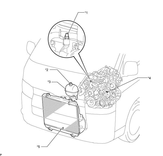
Text in Illustration *1 Bleeder Plug *2 Radiator Cap Sub-assembly *3 Radiator Reserve Tank Assembly *4 Cylinder Block Drain Cock Plug *5 Radiator Drain Cock Plug - - -
Remove the radiator cap sub-assembly.
-
Loosen the cylinder block drain cock plug, and drain the engine coolant.
-
Tighten the radiator drain cock plug.
-
Tighten the cylinder block drain cock plug.
- Torque:
- 13 N*m { 130 kgf*cm, 9 ft.*lbf }
-
Disconnect the hose from the radiator drain cock.
-
-
REMOVE SEAT TRACK COVER LH
-
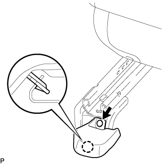
Using a clip remover, remove the clip.
-
Detach the claw and remove the seat track cover LH.
-
-
REMOVE FRONT SEAT ASSEMBLY RH
-
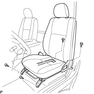
Move the front seat assembly fully forward.
-
Remove the 2 bolts on the rear side of the seat.
-
Move the front seat assembly to the rearmost position.
-
Remove the 2 bolts on the front side of the seat.
-
Move the front seat assembly to the center of the seat slide rail. Set the seatback in the upright position.
-
Disconnect the front seat inner belt assembly connector.
-
Remove the front seat assembly.
-
-
REMOVE FRONT DOOR SCUFF PLATE RH
-
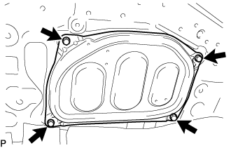
REMOVE ENGINE SERVICE HOLE SUB COVER SUB-ASSEMBLY
-
Fold back the floor carpet.
-
Remove the 5 bolts and engine service hole sub cover sub-assembly.
-
-
REMOVE TRANSMISSION SERVICE HOLE COVER SUB-ASSEMBLY
-
Remove the 2 seat belt anchor covers.
-
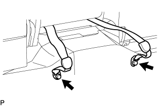
Remove the 2 bolts and disconnect the front center seat belt assembly RH and front center seat lap type belt assembly.
-
Detach the clips and fold back the carpet.
-
Remove the 4 bolts and transmission service hole cover sub-assembly from the body.
-
-
REMOVE DIESEL THROTTLE BODY ASSEMBLY
-
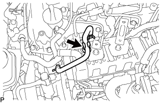
REMOVE NO. 16 WATER BY-PASS HOSE
-
Slide the 2 clamps and remove the No. 16 water by-pass hose from the No. 1 EGR cooler and No. 2 water by-pass pipe.
-
-
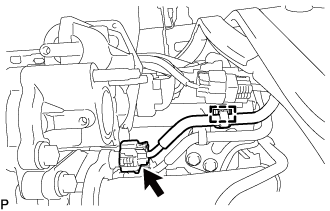
REMOVE DIESEL TURBO PRESSURE SENSOR
-
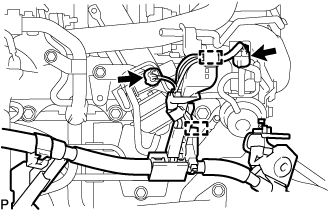
Disconnect the connector from the diesel turbo pressure sensor.
-
Remove the bolt and diesel turbo pressure sensor from the No. 3 water by-pass pipe sub-assembly.
-
-
DISCONNECT ENGINE WIRE
-
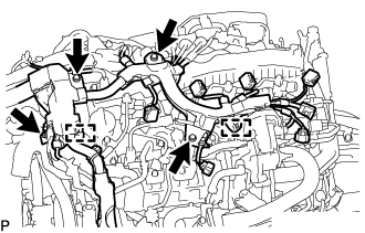
Detach the 2 clamps and disconnect the 2 connectors from the turbocharger sub-assembly.
-
Disconnect the connector from the camshaft position sensor.
-
Detach the clamp and disconnect the connector from the differential pressure sensor.
-
Disconnect the 3 connectors from the exhaust gas temperature sensors.
-
Disconnect the connector from the exhaust fuel addition injector assembly.
-
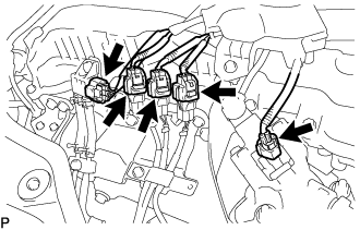
Disconnect the 4 connectors from the 4 injector assemblies.
-
Disconnect the electric EGR control valve assembly.
-
Disconnect the connector from the glow plug connector.
-
Disconnect the connector from the sensor wire of common rail assembly.
-
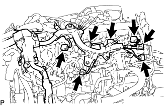
Detach the 2 clamps and remove the 4 bolts.
-
Disconnect the connector from the swirl control valve.
-
Disconnect the connector from the vacuum control valve set.
-
Detach the 2 clamps and disconnect the engine wire from the engine assembly.
-
-
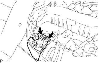
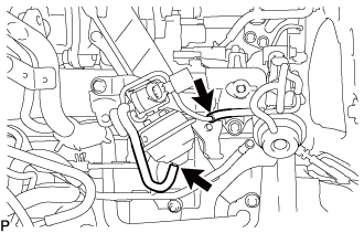
REMOVE EGR VALVE BRACKET
-
Remove the bolt, nut and EGR valve bracket from the electric EGR control valve assembly and intake manifold.
-
-
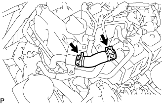
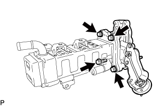
REMOVE NO. 2 EGR PIPE
-
Remove the bolt, 4 nuts and No. 2 EGR pipe from the electric EGR control valve assembly and intake manifold.
-
Remove the 2 gaskets.
-
-
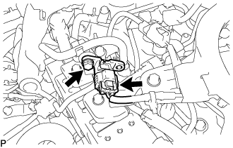
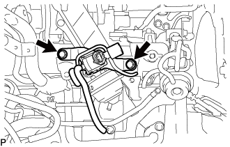
REMOVE ELECTRIC EGR CONTROL VALVE ASSEMBLY
-
Detach the clamp and disconnect the connector from the common rail assembly.
-
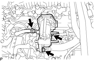
Slide the clamp and disconnect the No. 9 water by-pass hose from the electric EGR control valve assembly.
-
Remove the 2 bolts and electric EGR control valve assembly.
-
Remove the gasket.
-
-
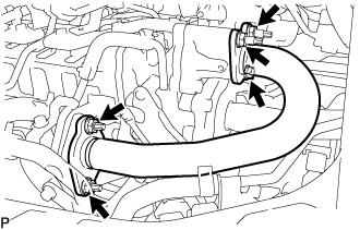
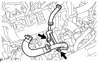
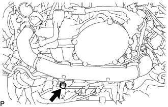
REMOVE NO. 3 WATER BY-PASS PIPE SUB-ASSEMBLY
-
Disconnect the No. 4 fuel hose from the No. 3 water by-pass pipe sub-assembly.
-
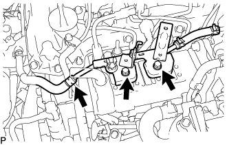
Slide the clamp and disconnect the No. 8 water by-pass hose from the No. 3 water by-pass pipe sub-assembly.
-
Remove the 2 bolts and No. 3 water by-pass pipe sub-assembly from the No. 1 EGR cooler.
-
-
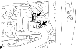
DISCONNECT NO. 4 WATER BY-PASS PIPE SUB-ASSEMBLY
-
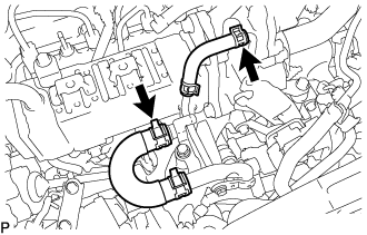
Slide the clamp and disconnect the No. 7 water by-pass hose from the No. 1 EGR cooler.
-
Slide the clamp and disconnect the water hose from the No. 2 EGR valve assembly.
-
Remove the 2 bolts and disconnect the No. 4 water by-pass pipe sub-assembly from the intake manifold.
-
-
REMOVE EGR PIPE INSULATOR
-
Remove the 2 bolts and EGR pipe insulator from the cylinder head sub-assembly.
-
-
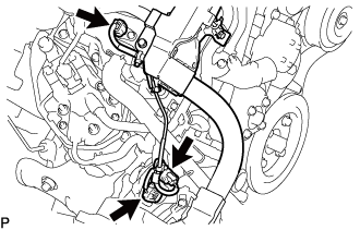
REMOVE NO. 1 EGR PIPE SUB-ASSEMBLY
-
Remove the bolt and disconnect the No. 1 EGR pipe sub-assembly from the vacuum transmitting pipe sub-assembly.
-
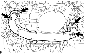
Remove the 4 nuts and the No. 1 EGR pipe sub-assembly from the exhaust manifold and EGR valve adapter.
-
Remove the 2 gaskets.
-
Using an E8 "TORX" socket wrench, remove the 2 stud bolts from the exhaust manifold.
-
-
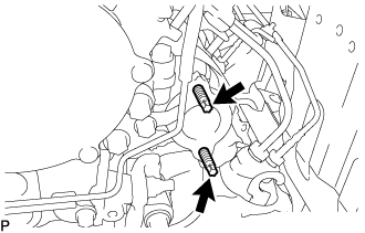
REMOVE VACUUM CONTROL VALVE SET
-
Disconnect the connector from the vacuum control valve set.
-
Disconnect the 2 vacuum hoses from the vacuum control valve set and No. 2 EGR valve assembly.
-
Remove the 2 bolts and vacuum control valve set from the intake manifold.
-
-
REMOVE NO. 1 EGR COOLER WITH NO. 2 EGR VALVE ASSEMBLY
-
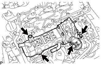
Remove the 4 bolts and No. 1 EGR cooler with No. 2 EGR valve assembly from the intake manifold.
-
-
REMOVE EGR VALVE ADAPTER
-
Remove the 2 bolts and EGR valve adapter from the No. 2 EGR valve assembly.
-
Remove the gasket.
-
-
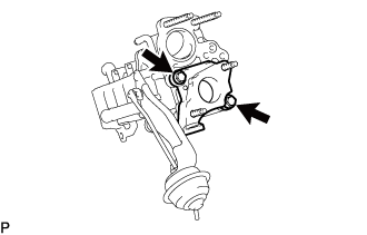
REMOVE NO. 2 EGR VALVE ASSEMBLY
-
Remove the 4 bolts and No. 2 EGR valve assembly from the No. 1 EGR cooler.
-
Remove the gasket.
-
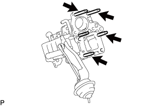
Using an E8 "TORX" socket wrench, remove the 4 stud bolts from the No. 2 EGR valve assembly.
-