EGR COOLER INSTALLATION
-
INSTALL NO. 1 EGR COOLER
-
Install a new gasket and the No. 1 EGR cooler to the No. 2 EGR valve assembly with electric EGR control valve assembly with the 4 bolts.
- Torque:
- 25 N*m { 255 kgf*cm, 18 ft.*lbf }
-
-
INSTALL NO. 1 EGR COOLER AND NO. 2 EGR VALVE ASSEMBLY WITH ELECTRIC EGR CONTROL VALVE ASSEMBLY
-
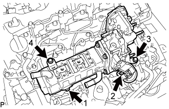
Temporarily install the No. 1 EGR cooler and No. 2 EGR valve assembly with electric EGR control valve assembly to the intake manifold with the 4 bolts.
-
Tighten the 4 bolts in the order shown in the illustration.
Tech Tips
Make sure to tighten the bolts in the order.
- Torque:
- 21 N*m { 214 kgf*cm, 15 ft.*lbf }
-
-
INSTALL VACUUM CONTROL VALVE SET
-
Install the vacuum control valve set to the intake manifold with the 2 bolts.
- Torque:
- 10 N*m { 102 kgf*cm, 7 ft.*lbf }
-
Connect the 2 vacuum hoses to the vacuum control valve set and No. 2 EGR valve assembly.
-
Connect the connector to the vacuum control valve set.
-
-
INSTALL NO. 1 EGR PIPE SUB-ASSEMBLY
-
Using an E8 "TORX" socket wrench, install 2 new stud bolts to the exhaust manifold.
- Torque:
- 10 N*m { 102 kgf*cm, 7 ft.*lbf }
-
Install 2 new gaskets and the No. 1 EGR pipe sub-assembly to the exhaust manifold and EGR valve adapter with 4 new nuts.
- Torque:
- 29 N*m { 296 kgf*cm, 21 ft.*lbf }
-
Connect the No. 1 EGR pipe sub-assembly to the vacuum transmitting pipe sub-assembly with the bolt.
- Torque:
- 10 N*m { 102 kgf*cm, 7 ft.*lbf }
-
-
INSTALL EGR PIPE INSULATOR
-
Install the EGR pipe insulator to the cylinder head sub-assembly with the 2 bolts.
- Torque:
- 21 N*m { 214 kgf*cm, 15 ft.*lbf }
-
-
CONNECT NO. 4 WATER BY-PASS PIPE SUB-ASSEMBLY
-
Connect the No. 4 water by-pass pipe sub-assembly to the intake manifold with the 2 bolts.
- Torque:
- 10 N*m { 102 kgf*cm, 7 ft.*lbf }
-
Connect the water hose to the No. 2 EGR valve assembly, and slide the clamp to secure the hose.
-
Connect the No. 7 water by-pass hose to the No. 1 EGR cooler, and slide the clamp to secure the hose.
-
-
INSTALL NO. 3 WATER BY-PASS PIPE SUB-ASSEMBLY
-
Install the No. 3 water by-pass pipe sub-assembly to the No. 1 EGR cooler with the 2 bolts.
- Torque:
- 10 N*m { 102 kgf*cm, 7 ft.*lbf }
-
Connect the No. 9 water by-pass hose to the electric EGR control valve assembly, and slide the clamp to secure the hose.
-
Connect the No. 8 water by-pass hose to the No. 3 water by-pass pipe sub-assembly, and slide the clamp to secure the hose.
-
Connect the No. 4 fuel hose to the No. 3 water by-pass pipe sub-assembly.
-
-
INSTALL NO. 2 EGR PIPE
-
Install 2 new gaskets and No. 2 EGR pipe to the electric EGR control valve assembly and the intake manifold with the 4 nuts.
- Torque:
- 29 N*m { 296 kgf*cm, 21 ft.*lbf }
-
-
INSTALL EGR VALVE BRACKET
-
Install the EGR valve bracket to the electric EGR control valve assembly and intake manifold with the bolt and nut.
- Torque:
- 21 N*m { 214 kgf*cm, 15 ft.*lbf }
-
-
CONNECT ENGINE WIRE
-
Connect the connector to the vacuum control valve set.
-
Connect the connector to the swirl control valve.
-
Attach the 2 clamps and connect the engine wire to the engine assembly.
-
Attach the 2 clamps and install the 4 bolts.
- Torque:
- 10 N*m { 102 kgf*cm, 7 ft.*lbf }
-
Connect the connector to the sensor wire of the common rail assembly.
-
Connect the connector to the glow plug connector.
-
Connect the connector to the electric EGR control valve assembly.
-
Connect the 4 connectors to the 4 injector assemblies.
-
Connect the connector to the exhaust fuel addition injector assembly.
-
Connect the 3 connectors to the 3 exhaust gas temperature sensors.
-
Connect the connector to the differential pressure sensor.
-
Connect the connector to the camshaft position sensor.
-
Attach the 2 clamps and connect the 2 connectors to the turbocharger sub-assembly.
-
-
INSTALL DIESEL TURBO PRESSURE SENSOR
-
Install the diesel turbo pressure sensor to the No. 3 water by-pass pipe sub-assembly with the bolt.
- Torque:
- 10 N*m { 102 kgf*cm, 7 ft.*lbf }
-
Connect the connector to the diesel turbo pressure sensor.
-
-
INSTALL NO. 16 WATER BY-PASS HOSE
-
Install the No. 16 water by-pass hose to the No. 1 EGR cooler and No. 2 water by-pass pipe, and slide the 2 clamps to secure the hoses.
-
-
INSTALL DIESEL THROTTLE BODY ASSEMBLY
-
ADD ENGINE COOLANT
-
Firmly tighten the drain plugs.
-
Fill the radiator reserve tank assembly with engine coolant to the top of the inlet.
Standard capacity 13.9 liters (14.6 US qts, 12.2 Imp qts) Note
Do not substitute plain water for engine coolant.
Tech Tips
-
Use of improper coolants may damage the engine cooling system.
-
Use only TOYOTA Super Long Life Coolant (SLLC) or similar high quality ethylene glycol based non-silicate, non-amine, non-nitrite, and non-borate coolant with long-life hybrid organic acid technology (coolant with long-life hybrid organic acid technology consists of a combination of low phosphates and organic acids).
-
-
Loosen the bleeder plug of the water outlet sub-assembly.
-
When air is bled and the engine coolant drains out, firmly tighten the bleeder plug.
- Torque:
- 8.0 N*m { 82 kgf*cm, 71 in.*lbf }
-
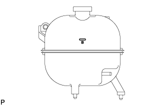
Add engine coolant up to the B line mark in the radiator reserve tank assembly and install the radiator cap sub-assembly.
-
Warm up the engine until the thermostat opens.
-
While the thermostat is open, circulate the engine coolant for several minutes.
Tech Tips
The thermostat open timing can be confirmed by pressing the No. 3 radiator hose by hand, and checking when the engine coolant starts to flow inside the hose.
-
-
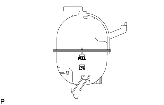
After the engine cools down, check that the engine coolant level is between the LOW and FULL line.
-
-
INSPECT FOR COOLANT LEAK
CAUTION:
Do not remove the radiator cap sub-assembly while the engine assembly and radiator assembly are still hot. Hot, pressurized engine coolant and steam may be released and cause serious burns.
-
Fill the radiator assembly with coolant and attach a radiator cap tester to the radiator.
-
Warm up the engine.
-
Using a radiator cap tester, increase the pressure inside the radiator assembly to 137 kPa (1.4 kgf/cm2, 19.9 psi), and check that the pressure does not drop.
Tech Tips
If the pressure drops, check the hoses, radiator assembly and engine water pump assembly for leaks. If no external leaks are found, check the heater core, cylinder block sub-assembly and cylinder head sub-assembly.
-
-
INSTALL TRANSMISSION SERVICE HOLE COVER SUB-ASSEMBLY
-
Install the transmission service hole cover sub-assembly to the body with the 4 bolts.
- Torque:
- 7.0 N*m { 71 kgf*cm, 62 in.*lbf }
-
Return the carpet to its original position and attach the clips.
-
Connect the front center seat belt assembly RH and front center seat lap type belt assembly with the 2 bolts.
- Torque:
- 42 N*m { 428 kgf*cm, 31 ft.*lbf }
-
Install the 2 seat belt anchor covers.
-
-
INSTALL ENGINE SERVICE HOLE SUB COVER SUB-ASSEMBLY
-
Install the engine service hole sub cover sub-assembly with the 5 bolts.
- Torque:
- 13 N*m { 133 kgf*cm, 10 ft.*lbf }
-
Return the floor carpet to its original position.
-
-
INSTALL FRONT DOOR SCUFF PLATE RH
-
INSTALL FRONT SEAT ASSEMBLY RH
-
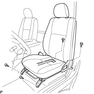
Connect the front seat inner belt assembly connector and install the front seat assembly.
-
Align the front seat assembly adjuster pin with the holes in the body.
-
Move the front seat assembly to the rearmost position.
Note
Make sure that the front seat assembly is securely locked.
-
Temporarily tighten the 2 bolts on the front side of the front seat assembly.
-
Move the front seat assembly fully forward.
Note
Make sure that the front seat assembly is securely locked.
-
Temporarily tighten the 2 bolts on the rear side of the front seat assembly.
-
Move the front seat assembly to the rearmost position.
Note
Make sure that the front seat assembly is securely locked.
-
Fully tighten the 2 bolts on the front side of the front seat assembly in the order of outer and inner side.
- Torque:
- 39 N*m { 398 kgf*cm, 29 ft.*lbf }
-
Move the front seat assembly fully forward.
Note
Make sure that the front seat assembly is securely locked.
-
Fully tighten the 2 bolts on the rear side of the front seat assembly in the order of outer and inner side.
- Torque:
- 39 N*m { 398 kgf*cm, 29 ft.*lbf }
-
-
INSTALL SEAT TRACK COVER LH
-
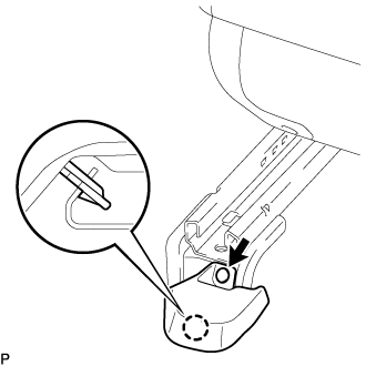
Attach the claw and install a new seat track cover LH with a new clip.
-