OUTER REAR VIEW MIRROR INSPECTION
PROCEDURE
-
INSPECT OUTER REAR VIEW MIRROR ASSEMBLY LH
-
Check the operation of the mirror surface.
-
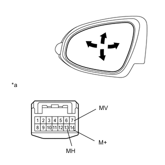
Text in Illustration *a Component without harness connected
(Outer Rear View Mirror Assembly LH)
Disconnect the outer rear view mirror assembly LH connector.
-
Apply battery voltage and check the operation of the mirror.
OK Measurement Condition Specified Condition Battery positive (+) → Terminal 7 (MV)
Battery negative (-) → Terminal 14 (M+)
Turns upward Battery positive (+) → Terminal 14 (M+)
Battery negative (-) → Terminal 7 (MV)
Turns downward Battery positive (+) → Terminal 13 (MH)
Battery negative (-) → Terminal 14 (M+)
Turns left Battery positive (+) → Terminal 14 (M+)
Battery negative (-) → Terminal 13 (MH)
Turns right If the result is not as specified, replace the outer rear view mirror assembly LH.
-
-
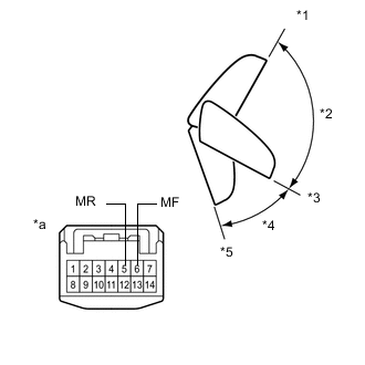
Check the operation of the retractable mirror. (w/ Retractable Mirror)
Note
-
Disconnect and reconnect the battery between each mirror position check.
-
The mirror position cannot be changed manually when the battery is connected. To change the mirror position manually, the battery must be disconnected first.
-
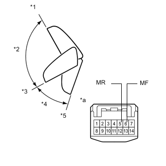
Text in Illustration *1 (A) Forward Position *2 (B) *3 (C) Driving position *4 (D) *5 (E) Retracted Position *a Component without harness connected
(Outer Rear View Mirror Assembly LH)
Disconnect the outer rear view mirror assembly LH connector.
-
For each position: Disconnect the battery, set the mirror position by hand, connect the battery, and check the retractable mirror's movement.
OK Tester Connection Condition Specified Condition Battery positive (+) → Terminal 5 (MR)
Battery negative (-) → Terminal 6 (MF)
Forward position (A) Moves from (A) to retracted position (E) Battery positive (+) → Terminal 6 (MF)
Battery negative (-) → Terminal 5 (MR)
Forward position (A) Does not move Battery positive (+) → Terminal 5 (MR)
Battery negative (-) → Terminal 6 (MF)
Position between forward position (A) and driving position (C) Moves from (B) to retracted position (E) Battery positive (+) → Terminal 6 (MF)
Battery negative (-) → Terminal 5 (MR)
Position between forward position (A) and driving position (C) Moves from (B) to forward position (A) Battery positive (+) → Terminal 5 (MR)
Battery negative (-) → Terminal 6 (MF)
Driving position (C) Moves from (C) to retracted position (E) Battery positive (+) → Terminal 6 (MF)
Battery negative (-) → Terminal 5 (MR)
Driving position (C) Does not move Battery positive (+) → Terminal 5 (MR)
Battery negative (-) → Terminal 6 (MF)
Position between driving position (C) and retracted position (E) Moves from (D) to retracted position (E) Battery positive (+) → Terminal 6 (MF)
Battery negative (-) → Terminal 5 (MR)
Position between driving position (C) and retracted position (E) Moves from (D) to driving position (C) Battery positive (+) → Terminal 5 (MR)
Battery negative (-) → Terminal 6 (MF)
Retracted position (E) Does not move Battery positive (+) → Terminal 6 (MF)
Battery negative (-) → Terminal 5 (MR)
Retracted position (E) Moves from (E) to driving position (C) If the result is not as specified, replace the outer rear view mirror assembly LH.
-
-
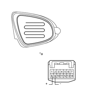
Check the operation of the mirror heater.
-
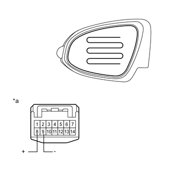
Text in Illustration *a Component without harness connected
(Outer Rear View Mirror Assembly LH)
Disconnect the outer rear view mirror assembly LH connector.
-
Measure the resistance according to the value(s) in the table below.
Standard Resistance Tester Connection Condition Specified Condition Terminal 8 (+) - Terminal 9 (-) 25°C (75°F) 12.0 to 15.0 Ω If the result is not as specified, check the outer mirror or replace the outer rear view mirror assembly LH.
-
-
-
INSPECT OUTER REAR VIEW MIRROR ASSEMBLY RH
-
Check the operation of the mirror surface.
-
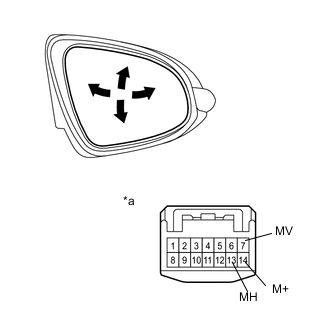
Text in Illustration *a Component without harness connected
(Outer Rear View Mirror Assembly RH)
Disconnect the outer rear view mirror assembly RH connector.
-
Apply battery voltage and check the operation of the mirror.
OK Measurement Condition Specified Condition Battery positive (+) → Terminal 7 (MV)
Battery negative (-) → Terminal 14 (M+)
Turns upward Battery positive (+) → Terminal 14 (M+)
Battery negative (-) → Terminal 7 (MV)
Turns downward Battery positive (+) → Terminal 13 (MH)
Battery negative (-) → Terminal 14 (M+)
Turns left Battery positive (+) → Terminal 14 (M+)
Battery negative (-) → Terminal 13 (MH)
Turns right If the result is not as specified, replace the outer rear view mirror assembly RH.
-
-
Check the operation of the retractable mirror. (w/ Retractable Mirror)
Note
-
Disconnect and reconnect the battery between each mirror position check.
-
The mirror position cannot be changed manually when the battery is connected. To change the mirror position manually, the battery must be disconnected first.
-
Text in Illustration *1 (A) Forward Position *2 (B) *3 (C) Driving position *4 (D) *5 (E) Retracted Position *a Component without harness connected
(Outer Rear View Mirror Assembly RH)
Disconnect the outer rear view mirror assembly RH connector.
-
For each position: Disconnect the battery, set the mirror position by hand, connect the battery, and check the retractable mirror's movement.
OK Tester Connection Condition Specified Condition Battery positive (+) → Terminal 5 (MR)
Battery negative (-) → Terminal 6 (MF)
Forward position (A) Moves from (A) to retracted position (E) Battery positive (+) → Terminal 6 (MF)
Battery negative (-) → Terminal 5 (MR)
Forward position (A) Does not move Battery positive (+) → Terminal 5 (MR)
Battery negative (-) → Terminal 6 (MF)
Position between forward position (A) and driving position (C) Moves from (B) to retracted position (E) Battery positive (+) → Terminal 6 (MF)
Battery negative (-) → Terminal 5 (MR)
Position between forward position (A) and driving position (C) Moves from (B) to forward position (A) Battery positive (+) → Terminal 5 (MR)
Battery negative (-) → Terminal 6 (MF)
Driving position (C) Moves from (C) to retracted position (E) Battery positive (+) → Terminal 6 (MF)
Battery negative (-) → Terminal 5 (MR)
Driving position (C) Does not move Battery positive (+) → Terminal 5 (MR)
Battery negative (-) → Terminal 6 (MF)
Position between driving position (C) and retracted position (E) Moves from (D) to retracted position (E) Battery positive (+) → Terminal 6 (MF)
Battery negative (-) → Terminal 5 (MR)
Position between driving position (C) and retracted position (E) Moves from (D) to driving position (C) Battery positive (+) → Terminal 5 (MR)
Battery negative (-) → Terminal 6 (MF)
Retracted position (E) Does not move Battery positive (+) → Terminal 6 (MF)
Battery negative (-) → Terminal 5 (MR)
Retracted position (E) Moves from (E) to driving position (C) If the result is not as specified, replace the outer rear view mirror assembly RH.
-
-
Check the operation of the mirror heater.
-
Text in Illustration *a Component without harness connected
(Outer Rear View Mirror Assembly RH)
Disconnect the outer rear view mirror assembly RH connector.
-
Measure the resistance according to the value(s) in the table below.
Standard Resistance Tester Connection Condition Specified Condition Terminal 8 (+) - Terminal 9 (-) 25°C (75°F) 12.0 to 15.0 Ω If the result is not as specified, check the outer mirror or replace the outer rear view mirror assembly RH.
-
-