LUGGAGE COMPARTMENT DOOR OPENER SYSTEM Luggage Compartment Door Opener does not Operate
DESCRIPTION
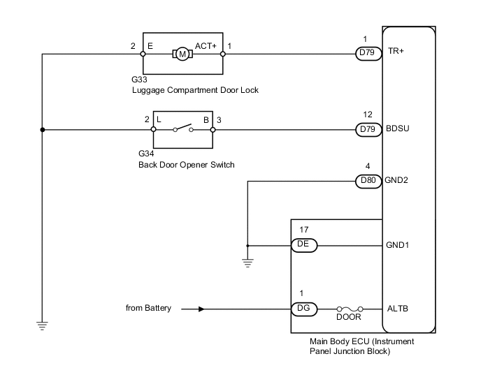
The main body ECU detects the condition of the back door opener switch.
WIRING DIAGRAM
CAUTION / NOTICE / HINT
Tech Tips
Inspect the fuses for circuits related to this system before performing the following inspection procedure.
PROCEDURE
-
PERFORM ACTIVE TEST USING INTELLIGENT TESTER
-
Select the Active Test, use the intelligent tester to generate a control command, and then check that the luggage compartment door lock motor operates Click here.
Main Body Tester Display Test Part Control Range Diagnostic Note Trunk and Back-Door Open Operate luggage compartment door latch release ON or OFF - Result Result Proceed to Luggage compartment door lock motor does not operate (door does not open) A Luggage compartment door lock motor operates (door opens) B
B 
READ VALUE USING INTELLIGENT TESTER (BACK DOOR OPENER SWITCH) Click here
A 
-
-
CHECK HARNESS AND CONNECTOR (MAIN BODY ECU - BATTERY AND BODY GROUND)
-
Disconnect the DG, DE and D80 ECU connectors.
-
Measure the voltage according to the value(s) in the table below.
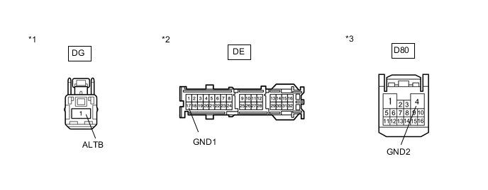
Standard Voltage Tester Connection Condition Specified Condition DG-1 (ALTB) - Body ground Always 11 to 14 V -
Measure the resistance according to the value(s) in the table below.
Standard Resistance Tester Connection Condition Specified Condition DE-17 (GND1) - Body ground Always Below 1 Ω D80-4 (GND2) - Body ground Always Below 1 Ω Text in Illustration *1 Front view of wire harness connector
(to Main Body ECU)
*2 Front view of wire harness connector
(to Main Body ECU)
*3 Front view of wire harness connector
(to Main Body ECU)
NG 
REPAIR OR REPLACE HARNESS OR CONNECTOR
OK
-
-
INSPECT LUGGAGE COMPARTMENT DOOR LOCK ASSEMBLY (DOOR LOCK MOTOR)
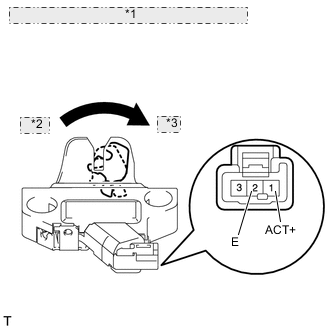
*1 Component without harness connected: (Luggage Compartment Door Lock) *2 Close *3 Open
-
Remove the luggage compartment door lock assembly Click here.
-
Move the luggage compartment door lock to the lock position.
-
Apply battery voltage and check the operation of the door lock motor.
OK Measurement Condition Specified Condition Battery positive (+) → Terminal 1
Battery negative (-) → Terminal 2
Opens
NG
REPLACE LUGGAGE COMPARTMENT DOOR LOCK ASSEMBLY Click here
OK
-
-
CHECK HARNESS AND CONNECTOR (MAIN BODY ECU AND BODY GROUND - LUGGAGE COMPARTMENT DOOR LOCK)
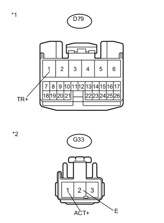
Text in Illustration *1 Front view of wire harness connector
(to Main Body ECU)
*2 Front view of wire harness connector
(to Luggage Compartment Door Lock)
-
Disconnect the D79 ECU connector.
-
Disconnect the G33 lock connector.
-
Measure the resistance according to the value(s) in the table below.
Standard Resistance Tester Connection Condition Specified Condition D79-1 (TR+) - G33-1 (ACT+) Always Below 1 Ω G33-2 (E) - Body ground Always Below 1 Ω D79-1 (TR+) - Body ground Always 10 kΩ or higher
OK
REPLACE MAIN BODY ECU
NG
REPAIR OR REPLACE HARNESS OR CONNECTOR
-
-
READ VALUE USING INTELLIGENT TESTER (BACK DOOR OPENER SWITCH)
-
Use the Data List to check if the back door opener switch is functioning properly.
Main Body Tester Display Measurement Item/Range Normal Condition Diagnostic Note Back Door Open Handle SW Back door opener switch signal / ON or OFF ON: Back door opener switch on
OFF: Back door opener switch off
- OK Tester display changes according to operation of back door opener switch.
OK
REPLACE MAIN BODY ECU
NG
-
-
INSPECT BACK DOOR OPENER SWITCH ASSEMBLY
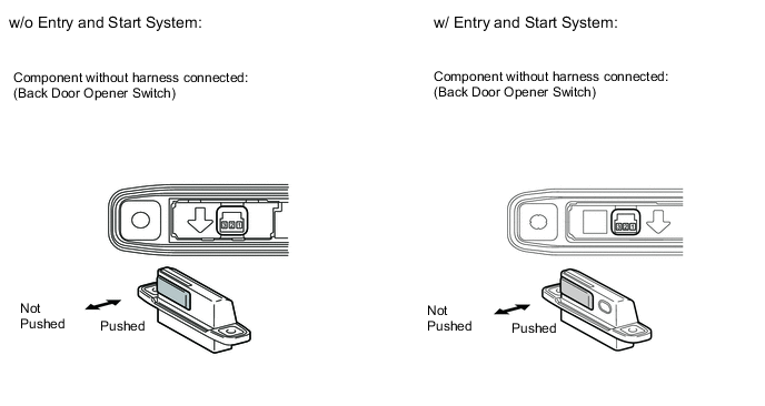
-
Remove the back door opener switch Click here.
-
Measure the resistance according to the value(s) in the table below.
Standard Resistance Tester Connection Switch Condition Specified Condition 2 - 3 Back door opener switch not pushed (Off) 10 kΩ or higher 2 - 3 Back door opener switch pushed (On) Below 1 Ω
NG
REPLACE BACK DOOR OPENER SWITCH ASSEMBLY Click here
OK
-
-
CHECK HARNESS AND CONNECTOR (BACK DOOR OPENER SWITCH - MAIN BODY ECU AND BODY GROUND)
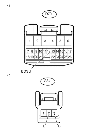
Text in Illustration *1 Front view of wire harness connector
(to Main Body ECU)
*2 Front view of wire harness connector
(to Back Door Opener Switch)
-
Disconnect the D79 main body ECU connector.
-
Measure the resistance according to the value(s) in the table below.
Standard Resistance Tester Connection Condition Specified Condition D79-12 (BDSU) - G34-3 (B) Always Below 1 Ω G34-2 (L) - Body ground Always Below 1 Ω D79-12 (BDSU) - Body ground Always 10 kΩ or higher
OK
REPLACE MAIN BODY ECU
NG
REPAIR OR REPLACE HARNESS OR CONNECTOR
-