COMPRESSOR(for 1WW, 2WW) INSTALLATION
PROCEDURE
-
ADJUST AMOUNT OF COMPRESSOR OIL
-
When replacing the compressor assembly with a new one:
Drain the following amount of compressor oil from the new compressor with pulley to be installed to adjust the amount of compressor oil.
Standard (The amount of oil in a new compressor assembly with pulley: 90 to 105 cc (3.04 to 3.55 fl.oz.)) - (The amount of oil in the removed compressor assembly with pulley) = The amount of oil to be removed from the new compressor assembly with pulley. Note
-
Since compressor oil remains in the pipes of the vehicle, if a new compressor is installed without removing some oil from the compressor, the oil amount becomes excessive. Excessive oil prevents heat exchange in the refrigerant cycle and causes refrigeration system failure.
-
Be sure to use ND-OIL 8 or equivalent for compressor oil.
-
Discharge the inert gas (helium) from the service valve.
-
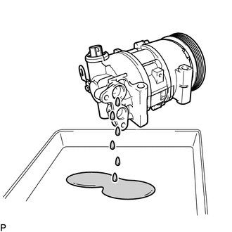
Remove the suction seal cap.
-
Position the suction port downward and slightly shake the compressor to drain oil.*1
Note
Be careful not to allow compressor oil to adhere to the pulley.
-
-
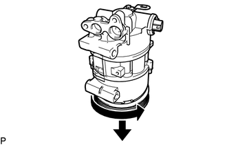
Position the pulley side downward and turn the pulley in the direction indicated by the arrow once every 2 seconds 10 times.*2
Note
Keep your face away from the compressor port because turning the pulley may cause gas or oil to spew out.
-
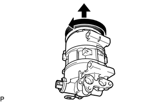
Quickly position the pulley side upward and turn the pulley in the direction indicated by the arrow once.*3
-
Repeat procedure *1.*4
-
Repeat procedures *2 through *4 approximately 5 times to drain the standard amount of oil.
-
-
INSTALL COMPRESSOR ASSEMBLY WITH PULLEY
-
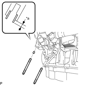
Text in Illustration *a Protrusion Height Using a plastic-faced hammer, tap in a new compressor pin.
Standard protrusion height 3.5 to 4.5 mm (0.138 to 0.177 in.) -
Using an E8 "TORX" socket wrench, install the 2 stud bolts.
- Torque:
- 9.8 N*m { 100 kgf*cm, 87 in.*lbf }
-
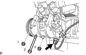
Install the bolt and 2 nuts.
- Torque:
- 25 N*m { 255 kgf*cm, 18 ft.*lbf }
Tech Tips
Tighten the bolts and nuts in the order shown in the illustration.
-
Connect the connector and attach the harness clamp.
-
-
CONNECT DISCHARGE HOSE SUB-ASSEMBLY
-
Remove the attached vinyl tape from the hose and compressor.
-
Apply sufficient compressor oil to a new O-ring and the fitting surface of the compressor assembly with pulley.
Compressor oil ND-OIL 8 or equivalent -
Install the O-ring to the discharge hose sub-assembly.
-
Connect the discharge hose sub-assembly to the compressor assembly with pulley with the bolt.
- Torque:
- 9.8 N*m { 100 kgf*cm, 87 in.*lbf }
-
-
CONNECT SUCTION HOSE SUB-ASSEMBLY
-
Remove the attached vinyl tape from the hose and compressor.
-
Apply sufficient compressor oil to a new O-ring and the fitting surface of the compressor assembly with pulley.
Compressor oil ND-OIL 8 or equivalent -
Install the O-ring to the suction hose sub-assembly.
-
Connect the suction hose sub-assembly to the compressor assembly with pulley with the bolt.
- Torque:
- 9.8 N*m { 100 kgf*cm, 87 in.*lbf }
-
-
INSTALL FAN AND GENERATOR V BELT
-
for 1WW:
Install the fan and generator V belt Click here.
-
for 2WW:
Install the fan and generator V belt Click here.
-
-
INSTALL RADIATOR ASSEMBLY
-
for 1WW:
Install the radiator assembly Click here.
-
for 2WW:
Install the radiator assembly Click here.
-
-
CHARGE REFRIGERANT
-
WARM UP ENGINE
-
INSPECT FOR COOLANT LEAK
-
for 1WW:
Inspect for coolant leak Click here.
-
for 2WW:
Inspect for coolant leak Click here.
-
-
CHECK FOR REFRIGERANT LEAK