COMPRESSOR INSTALLATION
PROCEDURE
-
ADJUST AMOUNT OF COMPRESSOR OIL
-
When replacing the compressor assembly with a new one:
Drain the following amount of compressor oil from the new compressor to be installed to adjust the amount of compressor oil.
Standard (Amount of oil to be drained when replacing) 50 cc (1.7 fl.oz) Note
-
Since compressor oil remains in the pipes of the vehicle, if a new compressor is installed without removing some oil from the compressor, the oil amount becomes excessive. Excessive oil prevents heat exchange in the refrigerant cycle and causes refrigeration system failure.
-
Be sure to use ND-OIL8 or equivalent for compressor oil.
-
Discharge the inert gas (helium) from the service valve.
-
Remove the suction seal cap.
-
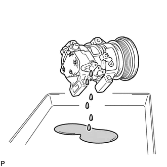
Position the suction port downward and slightly shake the compressor to drain oil.*1
Note
Be careful not to allow compressor oil to adhere to the pulley.
-
-
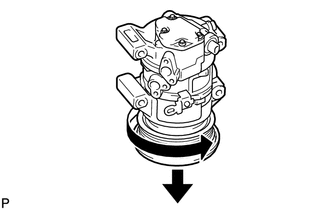
Position the pulley side downward and turn the pulley in the direction indicated by the arrow once every 2 seconds 10 times.*2
Note
Keep your face away from the compressor port because turning the pulley may cause gas or oil to spew out.
-
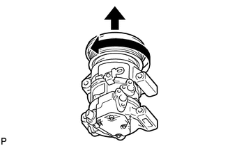
Quickly position the pulley side upward and turn the pulley in the direction indicated by the arrow once.*3
-
Repeat procedure *1.*4
-
Repeat procedures *2 through *4 approximately 5 times to drain the standard amount of oil.
-
-
INSTALL COMPRESSOR ASSEMBLY WITH PULLEY
-
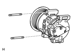
Using a "TORX" socket wrench (E8), install the compressor assembly with pulley with the 2 stud bolts.
- Torque:
- 9.8 N*m { 100 kgf*cm, 87 in.*lbf }
-
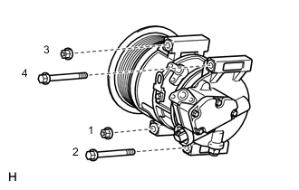
Install the 2 bolts and 2 nuts.
Tech Tips
Tighten the bolts and nuts in the order shown in the illustration.
- Torque:
- 25 N*m { 255 kgf*cm, 18 ft.*lbf }
-
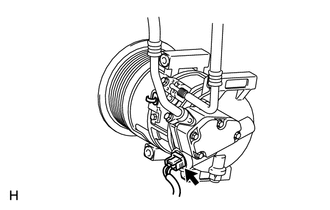
Connect the connector.
-
-
CONNECT SUCTION HOSE SUB-ASSEMBLY
-
Remove the attached vinyl tape from the hose and compressor.
-
Apply sufficient compressor oil to a new O-ring and the fitting surface of the compressor assembly with pulley.
Compressor oil ND-OIL 8 or equivalent -
Install the O-ring to the suction hose sub-assembly.
-
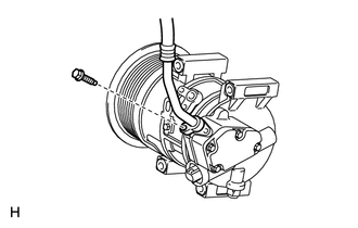
Connect the suction hose sub-assembly to the compressor assembly with pulley with the bolt.
- Torque:
- 9.8 N*m { 100 kgf*cm, 87 in.*lbf }
-
-
CONNECT DISCHARGE HOSE SUB-ASSEMBLY
-
Remove the attached vinyl tape from the hose and compressor.
-
Apply sufficient compressor oil to a new O-ring and the fitting surface of the compressor assembly with pulley.
Compressor oil ND-OIL 8 or equivalent -
Install the O-ring to the discharge hose sub-assembly.
-
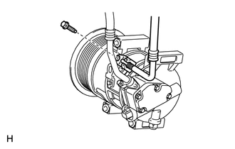
Connect the discharge hose sub-assembly to the compressor assembly with pulley with the bolt.
- Torque:
- 9.8 N*m { 100 kgf*cm, 87 in.*lbf }
-
-
CONNECT NO. 3 AIR HOSE
-
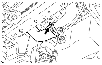
Connect the No. 3 air hose.
-
Tighten the hose clamp of the No. 3 air hose.
- Torque:
- 6.0 N*m { 61 kgf*cm, 53 in.*lbf }
-
-
INSTALL FAN AND GENERATOR V BELT
-
for 1AD-FTV:
Install the fan and generator V belt Click here.
-
for 2AD-FHV:
Install the fan and generator V belt Click here.
-
for 2AD-FTV:
Install the fan and generator V belt Click here.
-
-
INSTALL FRONT SUSPENSION MEMBER REINFORCEMENT RH
-
INSTALL REAR ENGINE UNDER COVER RH
-
INSTALL NO. 1 ENGINE UNDER COVER
-
INSTALL FRONT LOWER BUMPER ABSORBER
-
CHARGE REFRIGERANT
-
WARM UP ENGINE
-
INSPECT FOR REFRIGERANT LEAK
-
INSTALL RADIATOR SUPPORT OPENING COVER
-
INSTALL NO. 1 ENGINE COVER