COMBUSTION TYPE POWER HEATER SYSTEM Power Heater Switch Circuit
DESCRIPTION
When the power heater switch (air conditioning control assembly) is turned on, the ECU (heater assembly) sends a drive signal to the heater pump assembly. The heater assembly then receives the fuel necessary for combustion and starts operating.
WIRING DIAGRAM
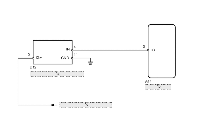
| *a | Air Conditioning Control Assembly |
| *b | Heater Assembly |
| *c | from Engine Stop and Start ECU |
CAUTION / NOTICE / HINT
Tech Tips
Before performing the following procedures, check the battery and confirm that they are operating normally.
PROCEDURE
-
INSPECT AIR CONDITIONING CONTROL ASSEMBLY
-
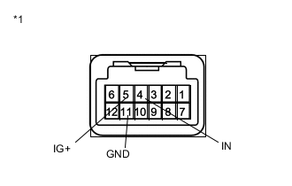
Text in Illustration *1 Component without harness connected
(Air Conditioning Control Assembly)
Remove the air conditioning control assembly Click here.
-
Measure the resistance according to the value(s) in the table below.
Standard Resistance Tester Connection Switch Condition Specified Condition 5 (IG+) - 4 (IN) Power heater switch on Below 1 Ω 5 (IG+) - 4 (IN) Power heater switch off 10 kΩ or higher -
Connect the positive (+) lead from the battery to terminal 5 (IG+) and the negative (-) lead to terminal 11 (GND), and check that the operation indicator comes on.
OK The power heater switch operation indicator comes on.
NG 
REPLACE AIR CONDITIONING CONTROL ASSEMBLY Click here
OK 
-
-
CHECK HARNESS AND CONNECTOR (AIR CONDITIONING CONTROL - BATTERY AND BODY GROUND)
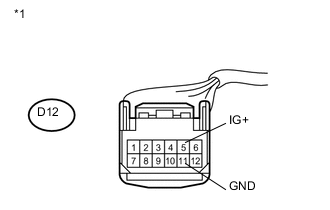
Text in Illustration *1 Front view of wire harness connector
(to Air Conditioning Control Assembly)
-
Disconnect the D12 air conditioning control assembly connector.
-
Measure the resistance according to the value(s) in the table below.
Standard Resistance Tester Connection Condition Specified Condition D12-11 (GND) - Body ground Always Below 1 Ω -
Measure the voltage according to the value(s) in the table below.
Standard Voltage Tester Connection Switch Condition Specified Condition D12-5 (IG+) - Body ground Ignition switch ON 10.5 to 16 V D12-5 (IG+) - Body ground Ignition switch off Below 1 V
NG
REPAIR OR REPLACE HARNESS OR CONNECTOR
OK
-
-
CHECK HARNESS AND CONNECTOR (HEATER ASSEMBLY - BATTERY)
-
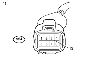
Text in Illustration *1 Front view of wire harness connector
(to Heater Assembly)
Disconnect the A54 heater assembly connector.
-
Measure the voltage according to the value(s) in the table below.
Standard Voltage Tester Connection Switch Condition Specified Condition A54-3 (IG) - Body ground Ignition switch ON
Power heater switch on
10.5 to 16 V A54-3 (IG) - Body ground Ignition switch ON
Power heater switch off
Below 1 V
OK
PROCEED TO NEXT SUSPECTED AREA SHOWN IN PROBLEM SYMPTOMS TABLE Click here
NG
REPAIR OR REPLACE HARNESS OR CONNECTOR
-