COMBUSTION TYPE POWER HEATER SYSTEM, Diagnostic DTC:047, 048, 049
| DTC Code | DTC Name |
|---|---|
| 047 | Short in Heater Fuel Pump Circuit |
| 048 | Heater Fuel Pump Malfunction |
| 049 | Heater Fuel Pump Output Error |
DESCRIPTION
| DTC Code | DTC Detection Condition | Trouble Area |
|---|---|---|
| 047 | A short is detected in the heater pump assembly circuit. |
|
| 048 | Operation stop of the heater pump assembly is detected (open in the circuit). |
|
| 049 | An error is detected in the output to the heater pump assembly. |
|
WIRING DIAGRAM
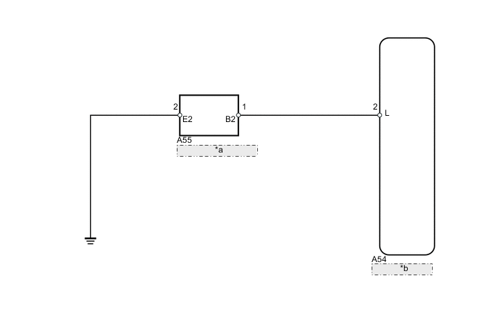
| *a | Heater Pump Assembly |
| *b | Heater Assembly |
PROCEDURE
-
CHECK HARNESS AND CONNECTOR (HEATER ASSEMBLY - HEATER PUMP ASSEMBLY)
-
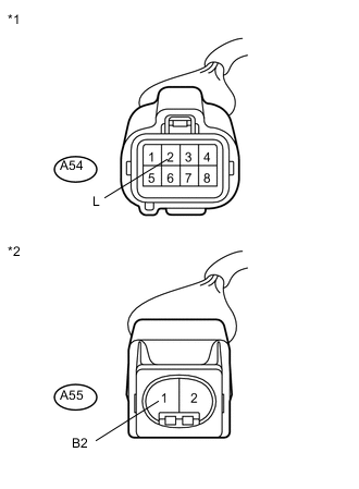
Text in Illustration *1 Front view of wire harness connector
(to Heater Assembly)
*2 Front view of wire harness connector
(to Heater Pump Assembly)
Disconnect the A54 heater assembly connector.
-
Disconnect the A55 heater pump assembly connector.
-
Measure the resistance according to the value(s) in the table below.
Standard Resistance Tester Connection Condition Specified Condition A54-2 (L) - A55-1 (B2) Always Below 1 Ω A54-2 (L) - Body ground Always 10 kΩ or higher
NG 
REPAIR OR REPLACE HARNESS OR CONNECTOR
OK 
-
-
CHECK HARNESS AND CONNECTOR (HEATER PUMP ASSEMBLY - BODY GROUND)
-
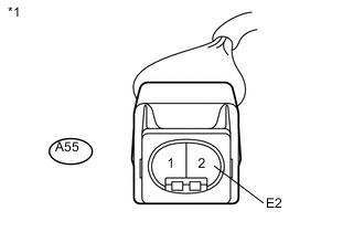
Text in Illustration *1 Front view of wire harness connector
(to Heater Pump Assembly)
Disconnect the A55 heater pump assembly connector.
-
Measure the resistance according to the value(s) in the table below.
Standard Resistance Tester Connection Condition Specified Condition A55-2 (E2) - Body ground Always Below 1 Ω
NG
REPAIR OR REPLACE HARNESS OR CONNECTOR
OK
-
-
INSPECT HEATER PUMP ASSEMBLY
-
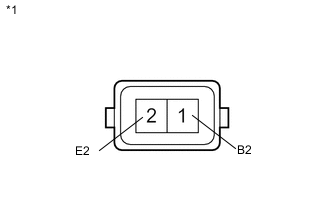
Text in Illustration *1 Component without harness connected
(Heater Pump Assembly)
Disconnect the A55 heater pump assembly connector.
-
Measure the resistance according to the value(s) in the table below.
Standard Resistance Tester Connection Condition Specified Condition 1 (B2) - 2 (E2) Always 9 to 12 Ω -
Connect the positive (+) lead from the battery to terminal 1 and the negative (-) lead to terminal 2, and check the pressure of the hose by hand.
Note
-
This inspection must be done quickly (within 10 seconds) to prevent damage to the heater pump assembly.
-
Always switch the voltage on and off on the battery side, not the heater pump assembly side.
-
Keep the heater pump assembly as far away from the battery as possible.
OK Pressure is applied to the hose. -
OK
REPLACE HEATER ASSEMBLY Click here
NG
REPLACE HEATER PUMP ASSEMBLY Click here
-