AIR CONDITIONING SYSTEM(for Manual Air Conditioning System), Diagnostic DTC:B14B2
| DTC Code | DTC Name |
|---|---|
| B14B2 | Lost Communication with Front Panel LIN |
DESCRIPTION
This circuit consists of the air conditioning control assembly and the air conditioning amplifier assembly. When the air conditioning control assembly is operated, signals are transmitted to the air conditioning amplifier assembly through the LIN communication system.
If the LIN communication system malfunctions, the air conditioning amplifier assembly does not operate when the air conditioning control assembly is operated.
| DTC Code | DTC Detection Condition | Trouble Area |
|---|---|---|
| B14B2 | Lost communication with the air conditioning control assembly. |
|
WIRING DIAGRAM
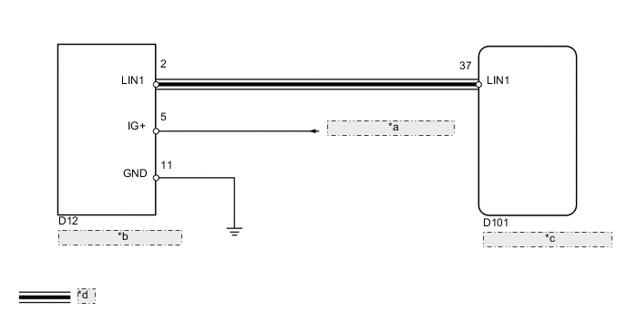
| *a | from Engine Stop and Start ECU |
| *b | Air Conditioning Control Assembly |
| *c | Air Conditioning Amplifier Assembly |
| *d | LIN Communication Line |
PROCEDURE
-
CHECK HARNESS AND CONNECTOR (AIR CONDITIONING CONTROL - AIR CONDITIONING AMPLIFIER)
-
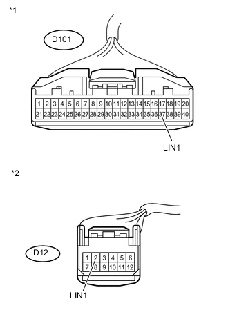
Text in Illustration *1 Front view of wire harness connector
(to Air Conditioning Amplifier Assembly)
*2 Front view of wire harness connector
(to Air Conditioning Control Assembly)
Disconnect the D101 amplifier connector.
-
Disconnect the D12 air conditioning control connector.
-
Measure the resistance according to the value(s) in the table below.
Standard Resistance Tester Connection Condition Specified Condition D12-2 (LIN1) - D101-37 (LIN1) Always Below 1 Ω D12-2 (LIN1) - Body ground Always 10 kΩ or higher
NG 
REPAIR OR REPLACE HARNESS OR CONNECTOR
OK 
-
-
CHECK HARNESS AND CONNECTOR (AIR CONDITIONING CONTROL - BATTERY AND BODY GROUND)
-
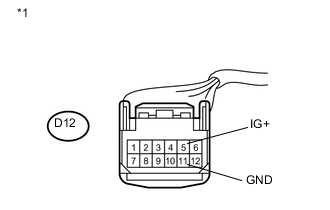
Text in Illustration *1 Front view of wire harness connector
(to Air Conditioning Control Assembly)
Disconnect the D12 air conditioning control connector.
-
Measure the voltage according to the value(s) in the table below.
Standard Voltage Tester Connection Switch Condition Specified Condition D12-5 (IG+) - D12-11 (GND) Ignition switch off Below 1 V D12-5 (IG+) - D12-11 (GND) Ignition switch ON 10.5 to 16 V -
Measure the resistance according to the value(s) in the table below.
Standard Resistance Tester Connection Condition Specified Condition D12-11 (GND) - Body ground Always Below 1 Ω
NG
REPAIR OR REPLACE HARNESS OR CONNECTOR
OK
-
-
REPLACE AIR CONDITIONING CONTROL ASSEMBLY
-
Replace the air conditioning control assembly with a new or normally functioning one Click here.
NEXT
-
-
CHECK AIR CONDITIONING CONTROL ASSEMBLY
-
Operate the air conditioning control to check that it functions properly.
OK Air conditioning control assembly operates normally.
OK
END (AIR CONDITIONING CONTROL ASSEMBLY IS DEFECTIVE)
NG
PROCEED TO NEXT SUSPECTED AREA SHOWN IN PROBLEM SYMPTOMS TABLE Click here
-