SEAT HEATER CONTROL(for Manual Seat) INSPECTION
PROCEDURE
-
INSPECT SEAT CLIMATE CONTROL CONTROLLER LH
-
Disconnect the seat climate control controller LH connectors.
-
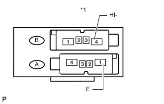
Text in Illustration *1 Component without harness connected
(Seat Climate Control Controller)
Measure the resistance according to the value(s) in the table below.
Standard Resistance Tester Connection Condition Specified Condition A1 (E) - B4 (HI-) Always Below 1 Ω If the result is not as specified, replace the seat climate control controller.
-

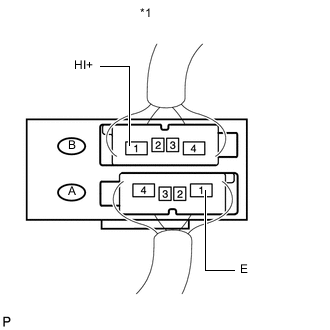
Text in Illustration *1 Front view of wire harness connector
(to Seat Climate Control Controller)
Measure the voltage and resistance according to the value(s) in the table below.
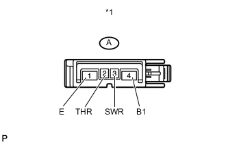
Standard Resistance Tester Connection Condition Specified Condition A1 (E) - Body ground Always Below 1 Ω Standard Voltage Tester Connection Switch Condition Specified Condition A4 (B) - A1 (E) Ignition switch ON 11 to 14 V A2 (THL) - A1 (E) Ignition switch ON, seat heater switch min → max Gradual increase from below 1 V to 11 to 14 V A3 (SWL) - A1 (E) Ignition switch ON, seat heater switch off → on Below 1 V → 11 to 14 V If the result is not as specified, repair or replace the wire harness or connector.
-
Connect the seat climate control controller LH connectors.
-
Text in Illustration *1 Component with harness connected
(Seat Climate Control Controller)
Measure the voltage according to the value(s) in the table below.
Standard Voltage Tester Connection Switch Condition Specified Condition B1 (HI+) - A1 (E) Ignition switch ON, seat heater switch min → max 11 to 14 V If the result is not as specified, replace the seat climate control controller.
-
-
INSPECT SEAT CLIMATE CONTROL CONTROLLER RH
-
Disconnect the seat climate control controller RH connectors.
-
Text in Illustration *1 Component without harness connected
(Seat Climate Control Controller)
Measure the resistance according to the value(s) in the table below.
Standard Resistance Tester Connection Condition Specified Condition A1 (E) - B4 (HI-) Always Below 1 Ω If the result is not as specified, replace the seat climate control controller.
-
Text in Illustration *1 Front view of wire harness connector
(to Seat Climate Control Controller)
Measure the voltage and resistance according to the value(s) in the table below.
Standard Resistance Tester Connection Condition Specified Condition A1 (E) - Body ground Always Below 1 Ω Standard Voltage Tester Connection Switch Condition Specified Condition A4 (B1) - A1 (E) Ignition switch ON 11 to 14 V A2 (THR) - A1 (E) Ignition switch ON, seat heater switch min → max Gradual increase from below 1 V to 11 to 14 V A3 (SWR) - A1 (E) Ignition switch ON, seat heater switch off → on Below 1 V → 11 to 14 V If the result is not as specified, repair or replace the wire harness or connector.
-
Connect the seat climate control controller RH connectors.
-
Text in Illustration *1 Component with harness connected
(Seat Climate Control Controller)
Measure the voltage according to the value(s) in the table below.
Standard Voltage Tester Connection Switch Condition Specified Condition B1 (HI+) - A1 (E) Ignition switch ON, seat heater switch min → max 11 to 14 V If the result is not as specified, replace the seat climate control controller.
-