FRONT POWER SEAT CONTROL SYSTEM Power Seat Position is not Memorized
DESCRIPTION
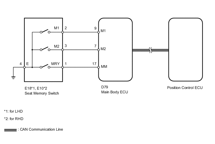
When the seat memory SET switch and a memory switch (M1 or M2) are pressed simultaneously, the main body ECU commands the position control ECU through CAN communication to record the value of each position sensor.
WIRING DIAGRAM
CAUTION / NOTICE / HINT
Note
-
First perform the communication function inspections in How to Proceed with Troubleshooting to confirm that there are no CAN communication malfunctions before troubleshooting this symptom.
-
As the door control battery is installed between the vehicle battery and main body ECU (instrument panel junction block assembly), first perform the inspections in On-Vehicle Inspection to confirm that there are no malfunctions in the power source circuit for the main body ECU (instrument panel junction block assembly) before performing this troubleshooting procedure Click here.
PROCEDURE
-
CHECK FRONT POWER SEAT CONTROL FUNCTION
-
Check that each function of the power seat operates normally by using the front power seat switches.
OK Each function of power seat operates normally by using seat switches.
NG 
GO TO PROBLEM SYMPTOMS TABLE Click here
OK 
-
-
CHECK SEAT MEMORY SWITCH FUNCTION
-
Perform a memory operation properly. Check that the buzzer sounds to indicate the completion of the memory operation.
Note
-
The seat position will not be recorded if the SET switch and both memory switches are pressed simultaneously.
-
If a memorizing operation has failed, release all switches. The seat memory function does not operate unless the switches are released.
OK Seat memory switch function operates normally. -
OK
END
NG
-
-
INSPECT SEAT MEMORY SWITCH
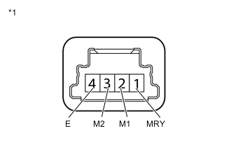
Text in Illustration *1 Component without harness connected
(Seat Memory Switch)
-
Remove the seat memory switch Click here.
-
Measure the resistance according to the value(s) in the table below.
Standard Resistance Tester Connection Switch Condition Specified Condition 2 (M1) - 4 (E) M1 switch pressed Below 1 Ω 3 (M2) - 4 (E) M2 switch pressed Below 1 Ω 1 (MRY) - 4 (E) SET switch pressed Below 1 Ω
NG
REPLACE SEAT MEMORY SWITCH Click here
OK
-
-
CHECK HARNESS AND CONNECTOR (SEAT MEMORY SWITCH - MAIN BODY ECU AND BODY GROUND)
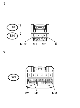
Text in Illustration *1 for LHD *2 for RHD *3 Front view of wire harness connector
(to Seat Memory Switch)
*4 Front view of wire harness connector
(to Main Body ECU)
-
Disconnect the E18*1 or E10*2 switch connector.
-
*1: for LHD
-
*2: for RHD
-
-
Disconnect the D79 ECU connector.
-
Measure the resistance according to the value(s) in the table below.
Standard Resistance for LHD Tester Connection Condition Specified Condition E18-2 (M1) - D79-9 (M1) Always Below 1 Ω E18-3 (M2) - D79-7 (M2) Always Below 1 Ω E18-1 (MRY) - D79-17 (MM) Always Below 1 Ω E18-4 (E) - Body ground Always Below 1 Ω E18-2 (M1) - Body ground Always 10 kΩ or higher E18-3 (M2) - Body ground Always 10 kΩ or higher E18-1 (MRY) - Body ground Always 10 kΩ or higher for RHD Tester Connection Condition Specified Condition E10-2 (M1) - D79-9 (M1) Always Below 1 Ω E10-3 (M2) - D79-7 (M2) Always Below 1 Ω E10-1 (MRY) - D79-17 (MM) Always Below 1 Ω E10-4 (E) - Body ground Always Below 1 Ω E10-2 (M1) - Body ground Always 10 kΩ or higher E10-3 (M2) - Body ground Always 10 kΩ or higher E10-1 (MRY) - Body ground Always 10 kΩ or higher
NG
REPAIR OR REPLACE HARNESS OR CONNECTOR
OK
-
-
CHECK MAIN BODY ECU (OPERATION)
-
After replacing the main body ECU, check that the front power seat control functions operate normally using the front power seat switches and seat memory switch.
OK Front power seat control functions operate normally.
OK
END (REPLACE MAIN BODY ECU)
NG
REPLACE POSITION CONTROL ECU ASSEMBLY Click here
-