PRE-CRASH SAFETY SYSTEM Pre-crash Safety System Circuit
DESCRIPTION
When the ignition switch is ON, power is supplied to the pre-crash safety city sensor.
WIRING DIAGRAM
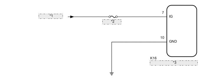
| *1 | from IG1 Relay |
| *2 | ECU-IG NO.1 |
| *3 | Pre-crash Safety City Sensor |
CAUTION / NOTICE / HINT
Note
Inspect the fuses for circuits related to this system before performing the following procedure.
PROCEDURE
-
CHECK HARNESS AND CONNECTOR (PRE-CRASH SAFETY CITY SENSOR - BATTERYAND BODY GROUND)
-
Check pre-crash safety city sensor.
Note
DTCs may be output when connectors are disconnected during inspection. Therefore, make sure to clear the DTCs using the GTS once the inspection has been completed.
-
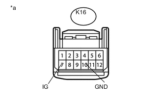
Text in Illustration *a Front view of wire harness connector
(to Pre-crash Safety City Sensor)
Disconnect the pre-crash safety city sensor connector.
-
Measure the voltage according to the value(s) in the table below.
Standard Voltage Tester Connection Switch Condition Specified Condition K16-7 (IG) - Body ground Ignition switch ON 11 to 14 V K16-7 (IG) - Body ground Ignition switch off Below 1 V -
Measure the resistance according to the value(s) in the table below.
Standard Resistance Tester Connection Condition Specified Condition K16-10 (GND) - Body ground Always Below 1 Ω
-
NG 
REPAIR OR REPLACE HARNESS OR CONNECTOR
OK 
-
-
CHECK CAN COMMUNICATION SYSTEM
-
Use the GTS to check if the CAN communication system is functioning normally Click here.
Result Result Proceed to CAN communication system DTCs are not output A CAN communication system DTCs are output B
A
PROCEED TO NEXT SUSPECTED AREA SHOWN IN PROBLEM SYMPTOMS TABLE Click here
B
GO TO CAN COMMUNICATION SYSTEM Click here
-