PRE-CRASH SAFETY SYSTEM, Diagnostic DTC:C1AA7
| DTC Code | DTC Name |
|---|---|
| C1AA7 | Skid Control Buzzer Circuit |
DESCRIPTION
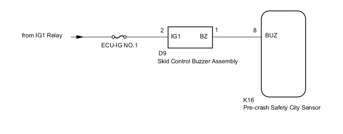
When the pre-crash safety city sensor uses pre-crash control to sound a warning, a buzzer signal is output to the skid control buzzer assembly. This DTC is output when the pre-crash safety city sensor detects a malfunction in the skid control buzzer assembly circuit.
| DTC Code | DTC Detection Condition | Trouble Area |
|---|---|---|
| C1AA7 | If either of the following is met with the ignition switch ON:
|
|
WIRING DIAGRAM
CAUTION / NOTICE / HINT
Note
-
Inspect the fuses for circuits related to this system before performing the following procedure.
-
When replacing the pre-crash safety city sensor, replace it with a new one. If an ECU which was installed to another vehicle is used, the information stored in the pre-crash safety city sensor will not match the information from the vehicle and, as a result, a DTC may be output.
-
When replacing the pre-crash safety city sensor with a new one, or performing removal, installation or replacement of the windshield glass, always perform "Recognition Camera/ Target Position Memory" and "Beam Axis Learning".
Perform adjustment with either "ONE TIME RECOGNITION" or "SEQUENTIAL RECOGNITION".
-
ONE TIME RECOGNITION: Click here
-
SEQUENTIAL RECOGNITION: Click here
PROCEDURE
-
INSPECT SKID CONTROL BUZZER ASSEMBLY
-
Remove the skid control buzzer assembly Click here.
-
Inspect the skid control buzzer assembly Click here.
NG 
REPLACE SKID CONTROL BUZZER ASSEMBLY Click here
OK 
-
-
CHECK HARNESS AND CONNECTOR (SKID CONTROL BUZZER ASSEMBLY - BATTERY)
-
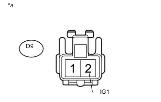
Text in Illustration *a Front view of wire harness connector
(to Skid Control Buzzer Assembly)
Disconnect the skid control buzzer assembly connector.
-
Measure the voltage according to the value(s) in the table below.
Standard Voltage Tester Connection Switch Condition Specified Condition D9-2 (IG1) - Body ground Ignition switch ON 11 to 14 V D9-2 (IG1) - Body ground Ignition switch off Below 1 V
NG
REPAIR OR REPLACE HARNESS OR CONNECTOR
OK
-
-
CHECK HARNESS AND CONNECTOR (SKID CONTROL BUZZER ASSEMBLY - PRE-CRASH SAFETY CITY SENSOR)
-
Disconnect the D9 skid control buzzer assembly connector.
-
Disconnect the K16 pre-crash safety city sensor connector.
-
Measure the resistance according to the value(s) in the table below.
Standard Resistance Tester Connection Condition Specified Condition D9-1 (BZ1) - K16-8 (BUZ) Always Below 1 Ω D9-1 (BZ1) - Body ground Always 100 kΩ or higher
OK
REPLACE PRE-CRASH SAFETY CITY SENSOR Click here
NG
REPAIR OR REPLACE HARNESS OR CONNECTOR
-