METER / GAUGE SYSTEM Fuel Receiver Gauge Malfunction
DESCRIPTION
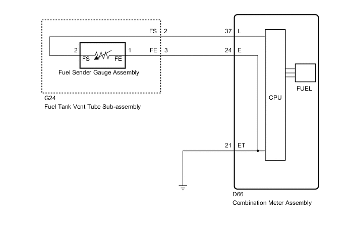
The fuel sender gauge assembly has a variable resistance mechanism. The resistance decreases when the fuel amount increases, and the resistance increases when the fuel amount decreases. The fuel receiver gauge changes based on the resistance of the fuel sender gauge assembly.
WIRING DIAGRAM
PROCEDURE
-
CHECK FOR DTC
-
Check for DTCs Click here.
Result Result Proceed to DTC B1500 is not output A DTC B1500 is output B
B 
Go to DTC B1500 Click here
A 
-
-
CHECK HARNESS AND CONNECTOR (COMBINATION METER ASSEMBLY - FUEL SUCTION WITH PUMP ASSEMBLY AND BODY GROUND)
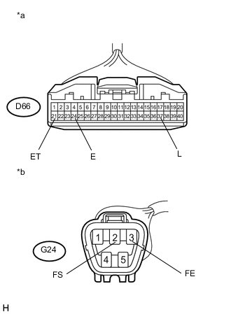
Text in Illustration *a Front view of wire harness connector
(to Combination Meter Assembly)
*b Front view of wire harness connector
(to Fuel Tank Vent Tube Sub-assembly)
-
Disconnect the D66 combination meter assembly connector.
-
Disconnect the G24 fuel suction with pump assembly connector.
-
Measure the resistance according to the value(s) in the table below.
Standard Resistance Tester Connection Condition Specified Condition D66-37 (L) - G24-2 (FS) Always Below 1 Ω D66-24 (E) - G24-3 (FE) Always Below 1 Ω D66-21 (ET) - Body ground Always Below 1 Ω D66-37 (L) or G24-2 (FS) - Body ground Always 10 kΩ or higher
NG
REPAIR OR REPLACE HARNESS OR CONNECTOR
OK
-
-
INSPECT FUEL TANK VENT TUBE SUB-ASSEMBLY
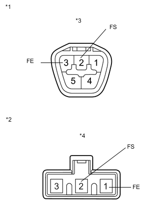
Text in Illustration *1 Upper side *2 Lower side (to fuel sender gauge assembly) *3 Connector A *4 Connector B
-
for 1AD-FTV:
Remove the fuel tank vent tube sub-assembly Click here.
-
for 2AD-FHV:
Remove the fuel tank vent tube sub-assembly Click here.
-
for 2AD-FTV:
Remove the fuel tank vent tube sub-assembly Click here.
-
Measure the resistance according to the value(s) in the table below.
Standard Resistance Tester Connection Condition Specified Condition A-2 (FS) - B-2 (FS) Always Below 1 Ω A-3 (FE) - B-1 (FE) Result Result Proceed to OK A NG (for 1AD-FTV) B NG (for 2AD-FHV) C NG (for 2AD-FTV) D
B
REPLACE FUEL TANK VENT TUBE SUB-ASSEMBLY Click here
C
REPLACE FUEL TANK VENT TUBE SUB-ASSEMBLY Click here
D
REPLACE FUEL TANK VENT TUBE SUB-ASSEMBLY Click here
A
-
-
INSPECT FUEL SENDER GAUGE ASSEMBLY
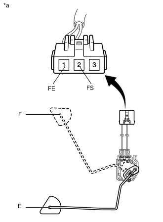
Text in Illustration *a Component without harness connected
(Fuel Sender Gauge Assembly)
-
for 1AD-FTV:
Remove the fuel sender gauge assembly Click here.
-
for 2AD-FHV:
Remove the fuel sender gauge assembly Click here.
-
for 2AD-FTV:
Remove the fuel sender gauge assembly Click here.
-
Measure the resistance according to the value(s) in the table below.
Standard Resistance Tester Connection Condition Specified Condition 2 (FS) - 1 (FE) Float Level F (Upper position) 13.5 to 16.5 Ω Float Level E (Lower position) 405.5 to 414.5 Ω Result Result Proceed to OK A NG (for 1AD-FTV) B NG (for 2AD-FHV) C NG (for 2AD-FTV) D
A
REPLACE COMBINATION METER ASSEMBLY Click here
B
REPLACE FUEL SENDER GAUGE ASSEMBLY Click here
C
REPLACE FUEL SENDER GAUGE ASSEMBLY Click here
D
REPLACE FUEL SENDER GAUGE ASSEMBLY Click here
-