LIGHTING SYSTEM TERMINALS OF ECU
-
CHECK MAIN BODY ECU (INSTRUMENT PANEL JUNCTION BLOCK ASSEMBLY)
-
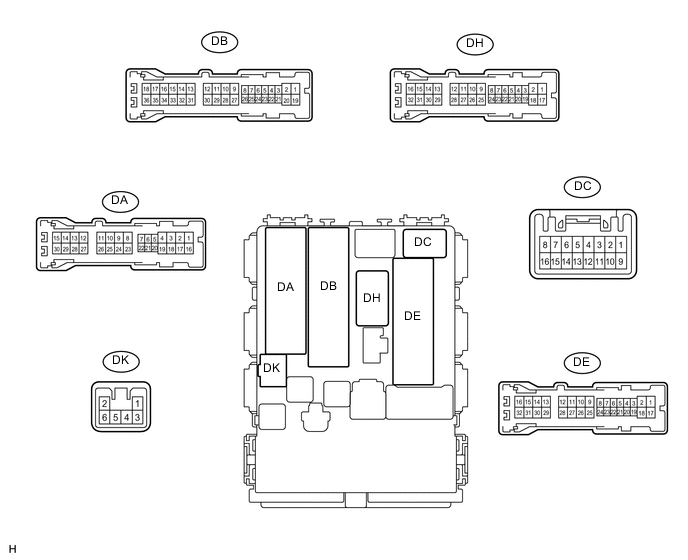
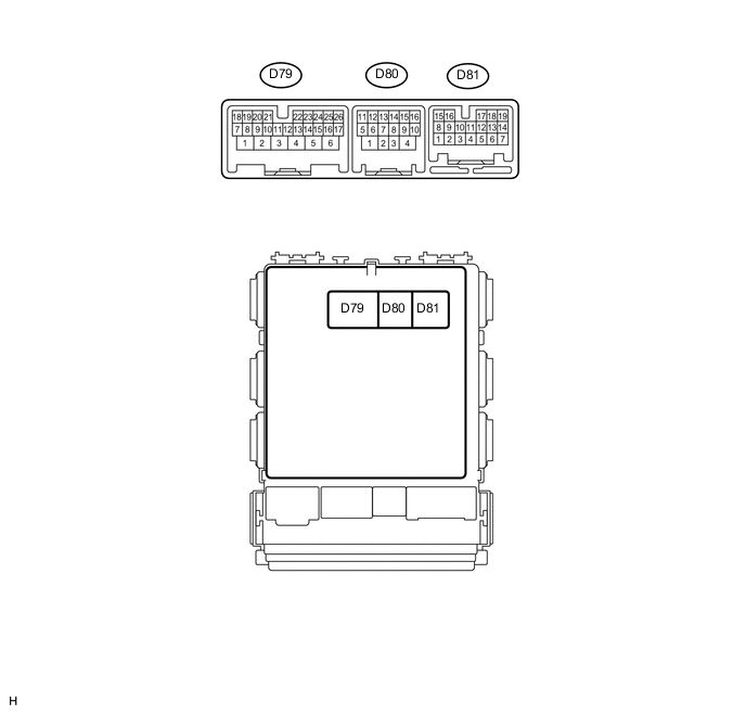
Disconnect the DE, DH and D80 main body ECU connectors.
-
Measure the voltage and resistance according to the value(s) in the table below.
Terminal No. (Symbol) Wiring Color Terminal Description Condition Specified Condition DH-12 (BECU) - Body ground W - Body ground Battery power supply Always 11 to 14 V DE-17 (GND1) - Body ground W-B - Body ground Body ground Always Below 1 Ω D80-4 (GND2) - Body ground W-B - Body ground Body ground Always Below 1 Ω If the result is not as specified, there may be a malfunction on the wire harness side.
-
Reconnect the DE, DH and D80 main body ECU connectors.
-
Measure the voltage according to the value(s) in the table below.
Terminal No. (Symbol) Wiring Color Terminal Description Condition Specified Condition DK-2 (ILE) - DE-17 (GND1) W - W-B Map light and No. 1 room light signal Battery saving control (interior light auto cut function) not operating, map light and No. 1 room light on using illuminated entry system Below 1 V Battery saving control (interior light auto cut function) not operating, map light and No. 1 room light off using illuminated entry system 11 to 14 V D79-2 (FSPT) - DE-17 (GND1)*1 W-B - W-B No. 1 interior illumination light signal No. 1 interior illumination light illumination on Below 1 V No. 1 interior illumination light illumination off 11 to 14 V D79-3 (DOMR) - DE-17 (GND1)*2,*3 P - W-B Battery saving control (interior light auto cut function) signal Battery saving control (interior light auto cut function) operating 11 to 14 V Battery saving control (interior light auto cut function) not operating Below 1 V D79-8 (LCTY) - DE-17 (GND1) SB - W-B Courtesy light switch signal
(Rear left door circuit)
Rear left door closed 11 to 14 V Rear left door open Below 1 V D79-19 (DOMR) - DE-17 (GND1)*4,*5 P - W-B Battery saving control (interior light auto cut function) signal Battery saving control (interior light auto cut function) operating 11 to 14 V Battery saving control (interior light auto cut function) not operating Below 1 V DA-21 (DCTY) - DE-17 (GND1)*6
DC-6 (DCTY) - DE-17 (GND1)*7
W - W-B
SB - W-B
Courtesy light switch signal
(Driver side door circuit)
Driver side door closed 11 to 14 V Driver side door open Below 1 V DE-19 (RCTY) - DE-17 (GND1) LG - W-B Courtesy light switch signal
(Rear right door circuit)
Rear right door closed 11 to 14 V Rear right door open Below 1 V DE-20 (PCTY) - DE-17 (GND1)*6
DA-24 (PCTY) - DE-17 (GND1)*7
Y - W-B
W - W-B
Courtesy light switch signal
(Passenger side door circuit)
Passenger side door closed 11 to 14 V Passenger side door open Below 1 V DA-7 (BCTY) - DE-17 (GND1)*8
DA-7 (LGCY) - DE-17 (GND1)*9
LG - W-B Courtesy light switch signal
(Back door circuit [for Wagon])
(Luggage compartment door circuit [for Sedan])
Back door closed (for Wagon)
Luggage compartment door closed (for Sedan)
11 to 14 V Back door open (for Wagon)
Luggage compartment door is open (for Sedan)
Below 1 V
-
*1: w/ No. 1 Interior Illumination Light
-
*2: except LHD Vehicles: w/o Power Tilt and Power Telescopic Steering Column System
-
*3: except RHD Vehicles: w/o Theft Deterrent System
-
*4: for LHD Vehicles: w/o Power Tilt and Power Telescopic Steering Column System
-
*5: for RHD Vehicles: w/o Theft Deterrent System
-
*6: for LHD
-
*7: for RHD
-
*8: for Wagon
-
*9: for Sedan
-
-