THEFT DETERRENT SYSTEM Glass Breakage Sensor Circuit
DESCRIPTION
When the glass breakage sensor detects that the back door glass, quarter window glass LH or quarter window glass RH is tapped or broken, the sensor will set off the alarm for 30 seconds.
WIRING DIAGRAM
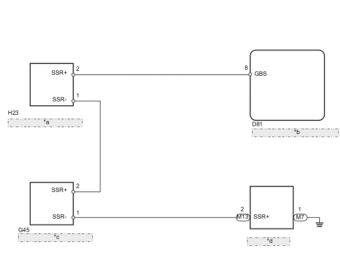
| *a | Quarter Window Assembly RH |
| *b | Main Body ECU (Instrument Panel Junction Block) |
| *c | Quarter Window Assembly LH |
| *d | Back Door Glass |
PROCEDURE
-
READ VALUE USING INTELLIGENT TESTER (GLASS BREAKAGE SENSOR)
-
Using the intelligent tester, read the Data List.
Main Body Tester Display Measurement Item/Range Normal Condition Diagnostic Note Sealed Glas Brak Sen Glass breakage sensor detection / ON or OFF ON: Glass breakage sensor operates
OFF: Glass breakage sensor does not operate
- OK ON (glass breakage sensor operates) appears on screen.
OK 
REPLACE MAIN BODY ECU (INSTRUMENT PANEL JUNCTION BLOCK)
NG 
-
-
CHECK HARNESS AND CONNECTOR (MAIN BODY ECU [INSTRUMENT PANEL JUNCTION BLOCK] - GLASS BREAKAGE SENSOR)
-
Disconnect the D81 ECU connector.
-
Disconnect the H23, G45 and M13 sensor connector.
-
Disconnect the M7 defogger connector.
-
Measure the resistance according to the value(s) in the table below.
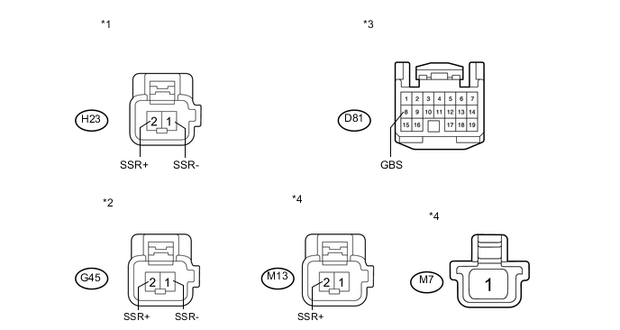
Standard Resistance Tester Connection Condition Specified Condition D81-8 (GBS) - H23-2 (SSR+) Always Below 1 Ω H23-1 (SSR-) - G45-2 (SSR+) Always Below 1 Ω G45-1 (SSR-) - M13-2 (SSR+) Always Below 1 Ω M7-1 - Body ground Always Below 1 Ω Text in Illustration *1 Front view of wire harness connector
(to Quarter Window Assembly RH)
*2 Front view of wire harness connector
(to Quarter Window Assembly LH)
*3 Front view of wire harness connector
(to Main Body ECU [Instrument Panel Junction Block])
*4 Front view of wire harness connector
(to Back Door Glass)
NG
REPAIR OR REPLACE HARNESS OR CONNECTOR
OK
-
-
INSPECT QUARTER WINDOW ASSEMBLY RH
-
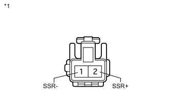
Text in Illustration *1 Component without harness connected
(Quarter Window Assembly RH)
Disconnect the H23 sensor connector.
-
Measure the resistance according to the value(s) in the table below.
Standard Resistance Tester Connection Condition Specified Condition 1 (SSR-) - 2 (SSR+) Always Below 1 Ω
NG
REPLACE QUARTER WINDOW ASSEMBLY RH Click here
OK
-
-
INSPECT QUARTER WINDOW ASSEMBLY LH
-
Text in Illustration *1 Component without harness connected
(Quarter Window Assembly LH)
Disconnect the G45 sensor connector.
-
Measure the resistance according to the value(s) in the table below.
Standard Resistance Tester Connection Condition Specified Condition 1 (SSR-) - 2 (SSR+) Always Below 1 Ω
NG
REPLACE QUARTER WINDOW ASSEMBLY LH Click here
OK
-
-
INSPECT BACK DOOR GLASS
-
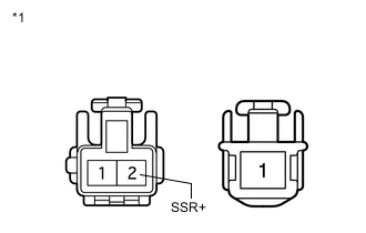
Text in Illustration *1 Front view of wire harness connector
(to Back Door Glass)
Disconnect the M13 sensor connector.
-
Disconnect the M7 defogger connector.
-
Measure the resistance according to the value(s) in the table below.
Standard Resistance Tester Connection Condition Specified Condition 2 (SSR+) - 1 Always Below 1 Ω
OK
REPLACE MAIN BODY ECU (INSTRUMENT PANEL JUNCTION BLOCK)
NG
REPLACE BACK DOOR GLASS Click here
-