ENTRY AND START SYSTEM(for Start Function), Diagnostic DTC:B2284, P0504
| DTC Code | DTC Name |
|---|---|
| B2284 | Brake Signal Malfunction |
| P0504 | Brake Switch "A" / "B" Correlation |
DESCRIPTION
This DTC is stored when the cable information of the brake signal and CAN information of the brake signal are inconsistent.
Tech Tips
When the power management control ECU is replaced with a new one and the cable is connected to the negative (-) battery terminal, the power source mode is reset to on (IG). When the battery is removed and reinstalled, the power source mode that was selected when the battery was removed is restored.
| DTC Code | DTC Detection Condition | Trouble Area |
|---|---|---|
| B2284 P0504 |
The cable information of the brake signal and CAN information of the brake signal are inconsistent. |
|
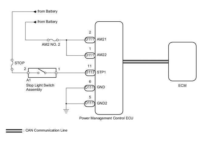
WIRING DIAGRAM
CAUTION / NOTICE / HINT
Note
-
When using the intelligent tester with the engine switch off to troubleshoot: Connect the intelligent tester to the vehicle, and turn a courtesy light switch on and off at 1.5 second intervals until communication between the intelligent tester and vehicle begins.
-
Before performing the inspection, check that there are no problems related to the CAN communication system and LIN communication system.
-
Inspect the fuses for circuits related to this system before performing the following inspection procedure.
Tech Tips
Check the connector connections and terminals to make sure that there are no abnormalities such as loose connections, deformation, etc.
PROCEDURE
-
CHECK HARNESS AND CONNECTOR (BATTERY - POWER MANAGEMENT CONTROL ECU)
-
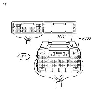
Text in Illustration *1 Rear view of wire harness connector
(to Power Management Control ECU)
Disconnect the D111 power management control ECU connector.
-
Measure the voltage according to the value(s) in the table below.
Standard Voltage Tester Connection Condition Specified Condition D111-2 (AM21) - Body ground Always 9.5 to 16 V D111-1 (AM22) - Body ground
NG 
REPAIR OR REPLACE HARNESS OR CONNECTOR
OK 
-
-
CHECK HARNESS AND CONNECTOR (POWER MANAGEMENT CONTROL ECU - BODY GROUND)
-
Disconnect the D111 power management control ECU connector.
-
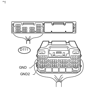
Text in Illustration *1 Rear view of wire harness connector
(to Power Management Control ECU)
Measure the resistance according to the value(s) in the table below.
Standard Resistance Tester Connection Condition Specified Condition D111-6 (GND) - Body ground Always Below 1 Ω D111-5 (GND2) - Body ground
NG
REPAIR OR REPLACE HARNESS OR CONNECTOR
OK
-
-
INSPECT STOP LIGHT SWITCH ASSEMBLY
-
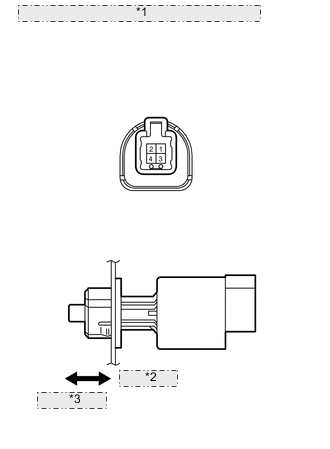
*1 Component without harness connected: (Stop Light Switch Assembly) *2 Pin pushed *3 Pin released Remove the stop light switch assembly Click here.
-
Measure the resistance according to the value(s) in the table below.
Standard Resistance Tester Connection Switch Condition Specified Condition 1 - 2 Pin pushed 10 kΩ higher Pin released Below 1 Ω 3 - 4 Pin pushed Below 1 Ω Pin released 10 kΩ higher
NG
REPLACE STOP LIGHT SWITCH ASSEMBLY Click here
OK
-
-
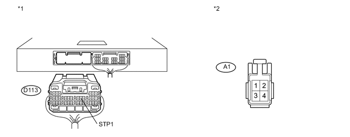
CHECK HARNESS AND CONNECTOR (POWER MANAGEMENT CONTROL ECU - STOP LIGHT SWITCH ASSEMBLY)
-
Disconnect the D113 power management control ECU connector.
-
Disconnect the A1 stop light switch assembly connector.
-
Measure the resistance according to the value(s) in the table below.
Standard Resistance Tester Connection Condition Specified Condition D113-11 (STP1) - A1-1 Always Below 1 Ω D113-11 (STP1) - Body ground Always 10 kΩ or higher -
Reconnect the A1 stop light switch assembly connector.
-
Measure the voltage according to the value(s) in the table below.
Standard Voltage Tester Connection Condition Specified Condition D113-11 (STP1) - Body ground Brake pedal not depressed Below 1.0 V Brake pedal depressed ((Voltage at terminal AM21 or AM22) minus 2.0 V) or higher Text in Illustration *1 Rear view of wire harness connector
(to Power Management Control ECU)
*2 Front view of wire harness connector
(to Stop Light Switch Assembly)
NG
REPAIR OR REPLACE HARNESS OR CONNECTOR
OK
-
-
READ VALUE USING INTELLIGENT TESTER (STOP LIGHT SWITCH)
-
Connect the intelligent tester to the DLC3.
-
Turn the engine switch on (IG).
-
Turn the intelligent tester on.
-
Enter the following menus: Body / Power Source Control / Data List.
-
According to the display on the intelligent tester, read the Data List.
Power Source Control Tester Display Measurement Item/Range Normal Condition Diagnostic Note Stop Light Switch1 Stop light switch 1 / ON or OFF ON: Brake pedal depressed
OFF: Brake pedal released
- OK ON (brake pedal depressed) or OFF (brake pedal released) appears on the screen according to the stop light switch condition. Tech Tips
If the result is not OK, refer to the ECD system.
-
for 1AD-FTV (for CCo): Click here.
-
for 1AD-FTV (for DPF): Click here.
-
for 2AD-FTV (w/ Gear Shift Indicator): Click here.
-
for 2AD-FTV (w/o Gear Shift Indicator): Click here.
-
for 2AD-FHV: Click here.
-
OK
REPLACE POWER MANAGEMENT CONTROL ECU Click here
NG
GO TO ECD SYSTEM (HOW TO PROCEED WITH TROUBLESHOOTING)
-