ENGINE IMMOBILISER SYSTEM(w/ Entry and Start System) Security Indicator Light Circuit
DESCRIPTION
-
When the theft deterrent system is in the disarmed state, the security indicator flashes continuously if the immobiliser system is set, but does not illuminate if the immobiliser system is not set.
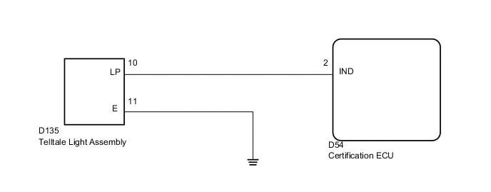
WIRING DIAGRAM
PROCEDURE
-
PERFORM ACTIVE TEST USING INTELLIGENT TESTER (SECURITY INDICATOR)
-
Check that the security indicator light illuminates when operating it with the Active Test.
Entry&Start Tester Display Test Part Control Range Diagnostic Note Security Indicator Security indicator ON / OFF - OK Security indicator illuminates.
OK 
REPLACE CERTIFICATION ECU
NG 
-
-
INSPECT TELLTALE LIGHT ASSEMBLY
-
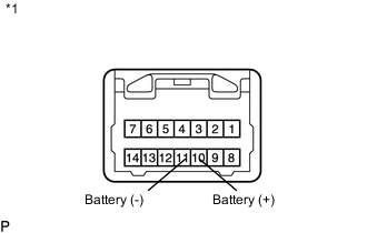
Text in Illustration *1 Component without harness connected
(Telltale Light Assembly)
Remove the telltale light assembly Click here.
-
Connect the positive (+) lead from the battery to terminal 10 and the negative (-) lead to terminal 11, and then check that security indicator illuminates.
OK Security indicator illuminates.
NG
REPLACE TELLTALE LIGHT ASSEMBLY Click here
OK
-
-
CHECK HARNESS AND CONNECTOR (TELLTALE LIGHT ASSEMBLY - CERTIFICATION ECU AND BODY GROUND)
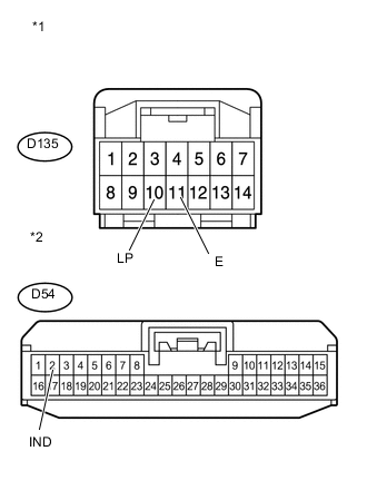
Text in Illustration *1 Front view of wire harness connector
(to Telltale Light Assembly)
*2 Front view of wire harness connector
(to Certification ECU)
-
Disconnect the D135 light connector.
-
Disconnect the D54 ECU connector.
-
Measure the resistance according to the value(s) in the table below.
Standard Resistance Tester Connection Condition Specified Condition D135-10 (LP) - D54-2 (IND) Always Below 1 Ω D135-11 (E) - Body ground Always Below 1 Ω D135-10 (LP) or D54-2 (IND) - Body ground Always 10 kΩ or higher
OK
REPLACE CERTIFICATION ECU
NG
REPAIR OR REPLACE HARNESS OR CONNECTOR
-