ENTRY AND START SYSTEM(for Entry Function) Front Passenger Side Door Entry Lock and Unlock Functions do not Operate
DESCRIPTION
When the front passenger side door entry lock and unlock functions do not operate, one of the following may be malfunctioning: 1) the power door lock system, 2) the front door outside handle (for passenger side), or 3) the certification ECU.
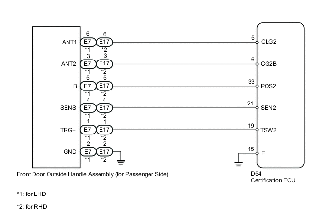
WIRING DIAGRAM
CAUTION / NOTICE / HINT
Note
-
The entry and start system (for entry function) uses a multiplex communication system (LIN communication system) and CAN communication system. Inspect the communication function by following How to Proceed with Troubleshooting Click here. Troubleshoot the entry and start system (for entry function) after confirming that the communication system is functioning properly.
-
When using the intelligent tester with the engine switch off to troubleshoot: Connect the intelligent tester to the DLC3, and turn a courtesy light switch on and off at 1.5-second intervals until communication between the tester and vehicle begins.
-
Check that there are no electrical key transmitters in the vehicle.
-
Before performing the inspection, check that DTC B1242 (wireless door lock control) is not output Click here.
-
When checking the entry lock operation multiple times, the lock operation may be limited to 2 consecutive operations according to the settings. In order to perform the entry lock operation 3 or more times, an unlock operation must be performed once (any type of unlock operation is sufficient). However, only consecutive entry lock operations are limited. Using the wireless lock or other types of lock operations, it is possible to perform consecutive lock operations without this limitation.
PROCEDURE
-
CHECK POWER DOOR LOCK OPERATION
-
When the master switch assembly door control switch is operated, check that the locked doors unlock Click here.
OK Door locks operate normally.
NG 
GO TO POWER DOOR LOCK CONTROL SYSTEM Click here
OK 
-
-
READ VALUE USING INTELLIGENT TESTER
-
Connect the intelligent tester to the DLC3.
-
Turn the engine switch on (IG).
-
Turn the intelligent tester on.
-
Enter the following menus: Body / Main Body / Data List.
-
Read the Data List according to the display on the intelligent tester.
Main Body Tester Display Measurement Item/Range Normal Condition Diagnostic Note P-Door Lock Pos SW Front passenger side door lock position switch signal / ON or OFF ON: Front passenger side door unlocked
OFF: Front passenger side door locked
- OK On the intelligent tester screen, the display changes between ON and OFF as shown in the chart above.
NG
GO TO POWER DOOR LOCK CONTROL SYSTEM (Proceed to Only Passenger Door LOCK/UNLOCK Functions do not Operate) Click here
OK
-
-
CHECK WAVE ENVIRONMENT
-
Bring the electrical key transmitter approximately 0.3 m (0.984 ft.) from the door outside handle (for front passenger side) and perform a front passenger side door entry lock and unlock operation check.
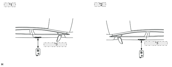
*1 for LHD: *2 for RHD: *3 Approximately 0.3 m Note
If the key is brought within 0.2 m (0.656 ft.) of the door handle, communication is not possible.
Tech Tips
-
When the electrical key transmitter is brought near the front passenger side door outside handle, the possibility of wave interference decreases, and it can be determined if wave interference is causing the problem symptom.
-
If the operation check is normal, the possibility of wave interference is high. Also, added vehicle components may cause wave interference. If installed, remove them and perform the operation check.
Result Result Proceed to Operation check fails A Operation check is normal B -
B
AFFECTED BY WAVE INTERFERENCE
A
-
-
CHECK HARNESS AND CONNECTOR (CERTIFICATION ECU - FRONT DOOR OUTSIDE HANDLE ASSEMBLY)
-
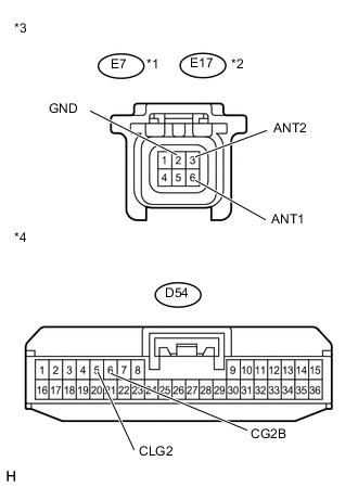
Text in Illustration *1 for LHD *2 for RHD *3 Front view of wire harness connector
(to Front Door Outside Handle Assembly (for Passenger Side))
*4 Front view of wire harness connector
(to Certification ECU)
Disconnect the D54 ECU connector.
-
Disconnect the E7*1 or E17*2 handle connector.
*1: for LHD
*2: for RHD
-
Measure the resistance according to the value(s) in the table below.
Standard Resistance for LHD Tester Connection Condition Specified Condition E7-3 (ANT2) - D54-6 (CG2B) Always Below 1 Ω E7-6 (ANT1) - D54-5 (CLG2) Always Below 1 Ω E7-2 (GND) - Body ground Always Below 1 Ω D54-6 (CG2B) - Body ground Always 10 kΩ or higher D54-5 (CLG2) - Body ground Always 10 kΩ or higher for RHD Tester Connection Condition Specified Condition E17-3 (ANT2) - D54-6 (CG2B) Always Below 1 Ω E17-6 (ANT1) - D54-5 (CLG2) Always Below 1 Ω E17-2 (GND) - Body ground Always Below 1 Ω D54-6 (CG2B) - Body ground Always 10 kΩ or higher D54-5 (CLG2) - Body ground Always 10 kΩ or higher
NG
REPAIR OR REPLACE HARNESS OR CONNECTOR
OK
-
-
INSPECT CERTIFICATION ECU
-
Reconnect the D54 ECU connector.
-
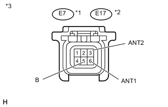
Text in Illustration *1 for LHD *2 for RHD *3 Front view of wire harness connector
(Front Door Outside Handle Assembly (for Passenger Side))
Measure the voltage according to the value(s) in the table below.
Standard Voltage for LHD Tester Connection Condition Specified Condition E7-3 (ANT2) - E7-6 (ANT1) Engine switch off, all doors closed, all doors locked with wireless door lock control and key not in cabin No pulse generation → Pulse generation for RHD Tester Connection Condition Specified Condition E17-3 (ANT2) - E17-6 (ANT1) Engine switch off, all doors closed, all doors locked with wireless door lock control and key not in cabin No pulse generation → Pulse generation -
Measure the voltage according to the value(s) in the table below.
Standard Voltage for LHD Tester Connection Switch Condition Specified Condition E7-5 (B) - Body ground Engine switch off → Engine switch on (IG) 9 to 12 V → Below 2 V for RHD Tester Connection Switch Condition Specified Condition E17-5 (B) - Body ground Engine switch off → Engine switch on (IG) 9 to 12 V → Below 2 V
NG
REPLACE CERTIFICATION ECU
OK
-
-
REPLACE FRONT DOOR OUTSIDE HANDLE ASSEMBLY (FOR PASSENGER SIDE)
-
Replace the front door outside handle assembly (for passenger side) Click here.
NEXT
-
-
CHECK FRONT DOOR OUTSIDE HANDLE ASSEMBLY (OPERATION)
-
Check that the entry functions operate normally Click here.
OK Entry functions operate normally.
OK
END (FRONT DOOR OUTSIDE HANDLE ASSEMBLY IS DEFECTIVE)
NG
REPLACE CERTIFICATION ECU
-