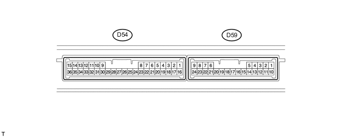
ENTRY AND START SYSTEM(for Entry Function) TERMINALS OF ECU
-
CHECK CERTIFICATION ECU
-
Disconnect the D54 ECU connector.
-
Measure the voltage and resistance according to the value(s) in the table below.
Terminal No. (Symbol) Wiring Color Terminal Description Condition Specified Condition D54-1 (+B) - D54-15 (E) R - W-B +B power supply Always 11 to 14 V D54-15 (E) - Body ground W-B - Body ground Ground Always Below 1 Ω D54-16 (IG) - D54-15 (E) L - W-B IG power supply Engine switch off → on (IG) Below 1 V → 11 to 14 V D54-17 (CUTB) - D54-15 (E) W - W-B +B power supply Always 11 to 14 V If the result is not as specified, there may be a malfunction on the wire harness side.
-
Reconnect the D54 ECU connector.
-
Measure the voltage according to the value(s) in the table below.
Terminal No. (Symbol) Wiring Color Terminal Description Condition Specified Condition D54-3 (CLG1) - D54-15 (E) R - W-B Door electrical key oscillator (for driver side) sensor signal Engine switch off, all doors closed, key not in cabin and transmitter lock switch not pressed → pressed No pulse generation → Pulse generation D54-4 (CG1B) - D54-15 (E) G - W-B Door electrical key oscillator (for driver side) sensor signal Engine switch off, all doors closed, key not in cabin and transmitter lock switch not pressed → pressed No pulse generation → Pulse generation D54-5 (CLG2) - D54-15 (E) W - W-B Door electrical key oscillator (for passenger side) sensor signal Engine switch off, all doors closed, key not in cabin and transmitter lock switch not pressed → pressed No pulse generation → Pulse generation D54-6 (CG2B) - D54-15 (E) P - W-B Door electrical key oscillator (for passenger side) sensor signal Engine switch off, all doors closed, key not in cabin and transmitter lock switch not pressed → pressed No pulse generation → Pulse generation D54-7 (CLG5) - D54-15 (E) B - W-B Indoor electrical key oscillator (front floor) sensor signal Engine switch off, all doors closed, key not in cabin and lock sensor off → on No pulse generation → Pulse generation D54-8 (CG5B) - D54-15 (E) W - W-B Indoor electrical key oscillator (front floor) sensor signal Engine switch off, all doors closed, key not in cabin and lock sensor off → on No pulse generation → Pulse generation D54-18 (TSW1) - D54-15 (E) B - W-B Entry lock sensor (for driver side) signal Engine switch off, all doors closed and lock sensor off → on Pulse generation → Below 2 V D54-19 (TSW2) - D54-15 (E) BR - W-B Entry lock sensor (for passenger side) signal Engine switch off, all doors closed and lock sensor off → on Pulse generation → Below 2 V D54-20 (SEN1) - D54-15 (E) R - W-B Entry unlock sensor (for driver side) detection signal Engine switch off, all doors locked, key not close enough to vehicle and unlock sensor (driver side) off → on Pulse generation → Below 2 V D54-21 (SEN2) - D54-15 (E) L - W-B Entry unlock sensor (for passenger side) detection signal Engine switch off, all doors locked, key not close enough to vehicle and unlock sensor (passenger side) off → on Pulse generation → Below 2 V D54-26 (CLG7) - D54-15 (E) BR - W-B Indoor electrical key oscillator (inside luggage) sensor signal Engine switch off, all doors closed, key not in cabin and lock sensor off → on No pulse generation → Pulse generation D54-27 (CG7B) - D54-15 (E) W - W-B Indoor electrical key oscillator (inside luggage) sensor signal Engine switch off, all doors closed, key not in cabin and lock sensor off → on No pulse generation → Pulse generation D54-24 (CLG6) - D54-15 (E) G - W-B Indoor electrical key oscillator (rear floor) sensor signal Engine switch off, all doors closed, key not in cabin and lock sensor off → on No pulse generation → Pulse generation D54-25 (CG6B) - D54-15 (E) R - W-B Indoor electrical key oscillator (rear floor) sensor signal Engine switch off, all doors closed, key not in cabin and lock sensor off → on No pulse generation → Pulse generation D54-32 (POS1) - D54-15 (E) V - W-B Entry unlock sensor (for driver side) output signal Engine switch off → on (IG) 9 to 14 V → Below 2 V D54-33 (POS2) - D54-15 (E) R - W-B Entry unlock sensor (for passenger side) output signal Engine switch off → on (IG) 9 to 14 V → Below 2 V D59-5 (RCO) - D54-15 (E) V - W-B Entry door control receiver power source Engine switch off, all doors closed and transmitter switch not pressed → pressed Below 1 V → 4.5 to 5.5 V D59-15 (RDA) - D54-15 (E) Y - W-B Entry door control receiver data input signal Engine switch off 11 to 14 V pulse generation at regular intervals D59-16 (RSSI) - D54-15 (E) R - W-B Entry door control receiver electric wave existence signal All doors locked, all doors closed and transmitter switch not pressed → pressed 11 to 14 V → Below 2 V D59-19 (CLG8) - D54-15 (E) V - W-B Outside electrical key oscillator (outside luggage) sensor signal Engine switch off, all doors closed and luggage compartment door*1 or back door*2 open switch off → on No pulse generation → Pulse generation D59-20 (CG8B) - D54-15 (E) W - W-B Outside electrical key oscillator (outside luggage) sensor signal Engine switch off, all doors closed and back door open switch or luggage compartment door open switch off → on No pulse generation → Pulse generation D54-22 (TSW5) - Body ground V - Body ground Luggage compartment door*1 or back door*2 open switch input Luggage compartment door*1 or back door*2 open switch off → on Pulse generation → Below 1 V D54-23 (TSW6) - Body ground R - Body ground Luggage compartment door*1 or back door*2 lock switch input Luggage compartment door*1 or back door*2 lock switch off → on Pulse generation → Below 1 V
-
*1: for Sedan
-
*2: for Wagon
If the result is not as specified, the certification ECU may have a malfunction.
-
-
-
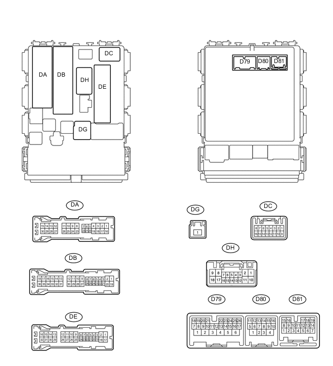
CHECK MAIN BODY ECU (INSTRUMENT PANEL JUNCTION BLOCK ASSEMBLY)
-
Disconnect the D79, D80, DB, DE and DG ECU connectors.
-
Measure the voltage and resistance according to the value(s) in the table below.
Terminal No. (Symbol) Wiring Color Terminal Description Condition Specified Condition D79-4 (BATB) - Body ground BR - Body ground Battery power supply Always 11 to 14 V DG-1 (ALTB) - Body ground W - Body ground Battery power supply Always 11 to 14 V DB-30 (BECU) - Body ground W - Body ground Power supply Always 11 to 14 V DE-17 (GND1) - Body ground W-B - Body ground Ground Always Below 1 Ω D80-4 (GND2) - Body ground W-B - Body ground Ground Always Below 1 Ω If the result is not as specified, there may be a malfunction on the wire harness side.
-
Reconnect the D79, D80, DB, DE and DG ECU connectors.
-
Measure the voltage according to the value(s) in the table below.
Terminal No. (Symbol) Wiring Color Terminal Description Condition Specified Condition DA-21 (DCTY)*1 - Body ground
DC-6 (DCTY)*2 - Body ground
W*1 - Body ground
SB*2 - Body ground
Driver side door courtesy light switch input Driver side door open Below 1 V Engine switch off and driver side door courtesy light switch off 11 to 14 V DE-20 (PCTY)*1 - Body ground
DA-24 (PCTY)*2 - Body ground
Y*1 - Body ground
W*2 - Body ground
Front passenger side door courtesy light switch input Front passenger side door open Below 1 V Engine switch off and passenger side door courtesy light switch off 11 to 14 V D79-8 (LCTY) - Body ground SB - Body ground Rear door courtesy light switch LH input Rear door LH open Below 1 V Engine switch off and rear door courtesy light switch LH off 11 to 14 V DE-19 (RCTY) - Body ground LG - Body ground Rear door courtesy light switch RH input Rear door RH open Below 1 V Engine switch off and rear door courtesy light switch RH off 11 to 14 V DA-7 (LGCY) - Body ground*3
DA-7 (BCTY) - Body ground*4
LG - Body ground Luggage compartment door*3 or back door*4 courtesy light switch input Luggage compartment door*3 or back door*4 open Below 1 V Engine switch off and luggage compartment door*3 or back door*4 closed 11 to 14 V DH-7 (L2) - Body ground SB - Body ground Driver side door lock key switch input Driver side door key cylinder lock position Below 1 V Engine switch off, all doors closed and driver side door key cylinder neutral position Pulse generation
(see waveform 1 or 2)
D79-25 (LSWD) - Body ground GR - Body ground Driver side door lock position switch input Driver side door unlocked Below 1 V Engine switch off, all doors closed and driver side door locked Pulse generation
(see waveform 3 or 4)
D79-10 (LWSP) - Body ground LG - Body ground Front passenger side door lock position switch input Front passenger side door unlocked Below 1 V Engine switch off, all doors closed and passenger side door locked Pulse generation
(see waveform 5 or 6)
D81-10 (LSR) - Body ground Y - Body ground Rear door lock position switch input Rear door unlocked Below 1 V Engine switch off, all doors closed and rear door locked Pulse generation
(see waveform 7 or 8)
D79-12 (BDSU) - Body ground V - Body ground Luggage compartment door*3 or back door*4 opener switch input Luggage compartment door*3 or back door*4 opener switch off Below 1 V Engine switch off, all doors closed and luggage compartment door*3 or back door*4 opener switch on Pulse generation (see waveform 9 or 10)
-
*1: for LHD
-
*2: for RHD
-
*3: for Sedan
-
*4: for Wagon
If the result is not as specified, the ECU may have a malfunction.
-
-
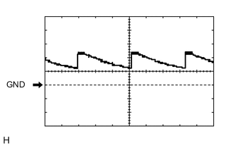
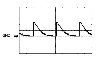
Using an oscilloscope, check waveform 1.
Waveform 1 (Reference) Item Content Terminal No. (Symbol) DH-7 (L2) - Body ground Tool Setting 5 V/DIV., 20 ms/DIV. Condition Engine switch off, all doors closed and driver side door key cylinder neutral position -
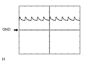
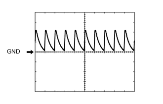
Using an oscilloscope, check waveform 2.
Waveform 2 (Reference) Item Content Terminal No. (Symbol) DH-7 (L2) - Body ground Tool Setting 5 V/DIV., 20 ms/DIV. Condition Engine switch off, all doors closed and driver side door key cylinder neutral position -
Using an oscilloscope, check waveform 3.
Waveform 3 (Reference) Item Content Terminal No. (Symbol) D79-25 (LSWD) - Body ground Tool Setting 5 V/DIV., 20 ms/DIV. Condition Engine switch off, all doors closed and driver side door locked -
Using an oscilloscope, check waveform 4.
Waveform 4 (Reference) Item Content Terminal No. (Symbol) D79-25 (LSWD) - Body ground Tool Setting 5 V/DIV., 20 ms/DIV. Condition Engine switch off, all doors closed and driver side door locked -
Using an oscilloscope, check waveform 5.
Waveform 5 (Reference) Item Content Terminal No. (Symbol) D79-10 (LWSP) - Body ground Tool Setting 5 V/DIV., 20 ms/DIV. Condition Engine switch off, all doors closed and passenger side door locked -
Using an oscilloscope, check waveform 6.
Waveform 6 (Reference) Item Content Terminal No. (Symbol) D79-10 (LWSP) - Body ground Tool Setting 5 V/DIV., 20 ms/DIV. Condition Engine switch off, all doors closed and passenger side door locked -
Using an oscilloscope, check waveform 7.
Waveform 7 (Reference) Item Content Terminal No. (Symbol) D81-10 (LSR) - Body ground Tool Setting 5 V/DIV., 20 ms/DIV. Condition Engine switch off, all doors closed and rear door locked -
Using an oscilloscope, check waveform 8.
Waveform 8 (Reference) Item Content Terminal No. (Symbol) D81-10 (LSR) - Body ground Tool Setting 5 V/DIV., 20 ms/DIV. Condition Engine switch off, all doors closed and rear door locked -
Using an oscilloscope, check waveform 9.
Waveform 9 (Reference) Item Content Terminal No. (Symbol) D79-12 (BDSU) - Body ground Tool Setting 5 V/DIV., 20 ms/DIV. Condition Engine switch off, all doors closed and luggage compartment door*3 or back door*4 opener switch on -
Using an oscilloscope, check waveform 10.
Waveform 10 (Reference) Item Content Terminal No. (Symbol) D79-12 (BDSU) - Body ground Tool Setting 5 V/DIV., 20 ms/DIV. Condition Engine switch off, all doors closed and luggage compartment door*3 or back door*4 opener switch on
-