CAN COMMUNICATION SYSTEM SYSTEM DIAGRAM
-
SYSTEM DIAGRAM
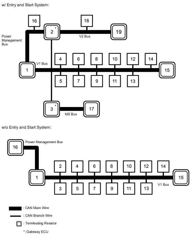
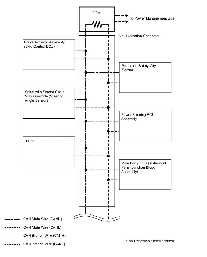
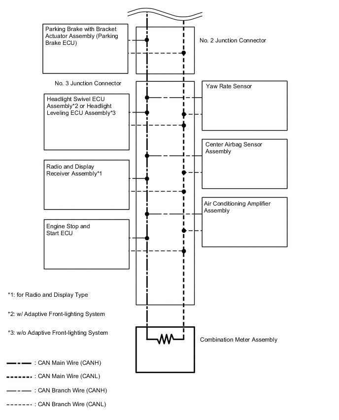
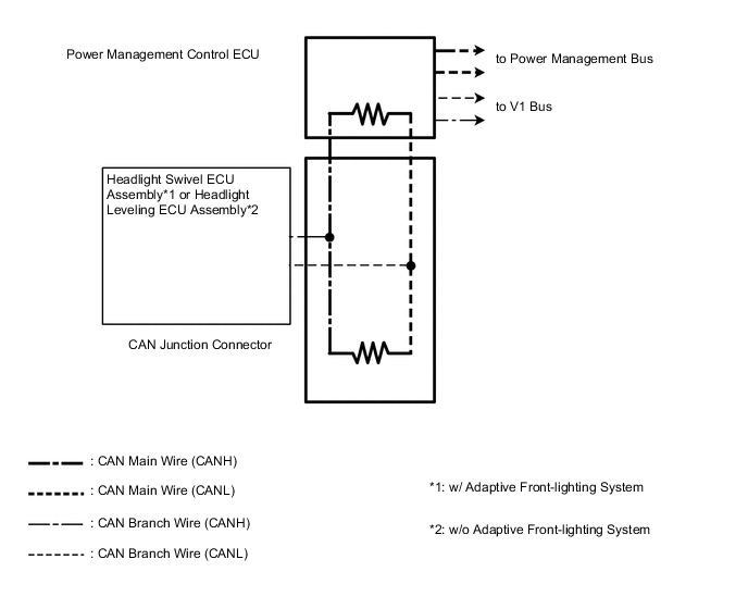
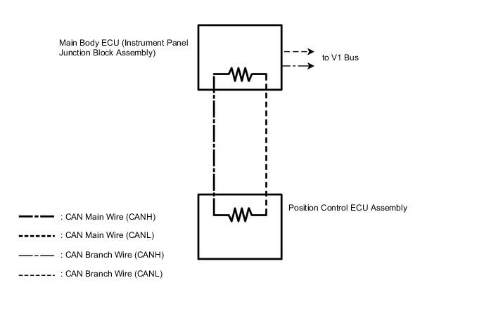
w/ Entry and Start System No. ECU/Sensor Name 1 ECM 2 Power management control ECU 3 Main body ECU (instrument panel junction block assembly) 4 Brake actuator assembly (skid control ECU) 5 Parking brake with bracket actuator assembly (parking brake ECU) 6 Certification ECU (smart key ECU assembly) 7 Power steering ECU assembly 8 Spiral with sensor cable sub-assembly (steering angle sensor) 9 Yaw rate sensor 10 DLC3 11 Center airbag sensor assembly 12 Radio and display receiver assembly*1 13 Pre-crash safety city sensor*2 14 Engine stop and start ECU 15 Combination meter assembly 16 Air conditioning amplifier assembly 17 Position control ECU assembly*3 18
-
Headlight swivel ECU assembly*4
-
Headlight leveling ECU assembly*5
19 CAN junction connector
-
*1: for Radio and Display Type
-
*2: w/ Pre-crash Safety System
-
*3: w/ Seat Position Memory System
-
*4: w/ Adaptive Front-lighting System
-
*5: w/o Adaptive Front-lighting System
w/o Entry and Start System No. ECU/Sensor Name 1 ECM 2 Main body ECU (instrument panel junction block assembly) 3 Brake actuator assembly (skid control ECU) 4 Parking brake with bracket actuator assembly (parking brake ECU) 5 Power steering ECU assembly 6 Air conditioning amplifier assembly 7 Spiral with sensor cable sub-assembly (steering angle sensor) 8 Yaw rate sensor 9 DLC3 10 Center airbag sensor assembly 11 Radio and display receiver assembly*1 12
-
Headlight swivel ECU assembly*2
-
Headlight leveling ECU assembly*3
13 Pre-crash safety city sensor*4 14 Engine stop and start ECU 15 Combination meter assembly 16 Power management control ECU
-
*1: for Radio and Display Type
-
*2: w/ Adaptive Front-lighting System
-
*3: w/o Adaptive Front-lighting System
-
*4: w/ Pre-crash Safety System
-
-
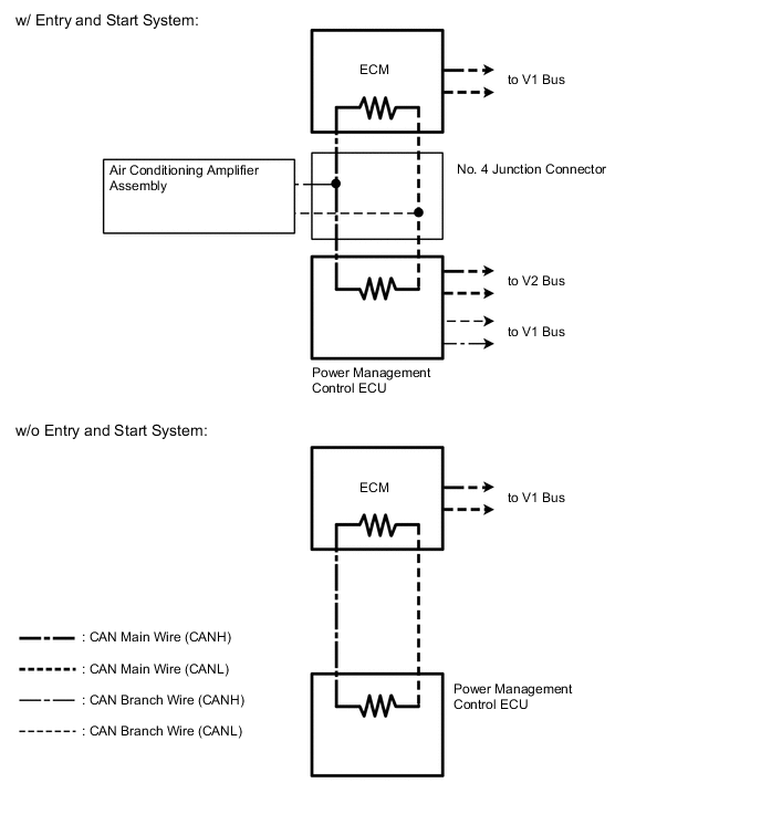
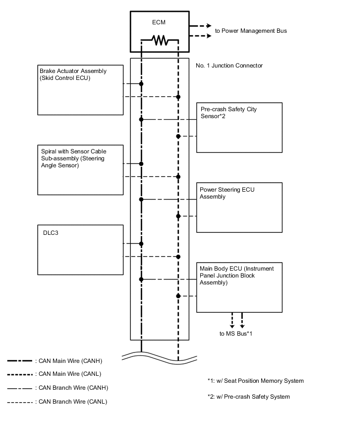
V1 Bus (w/ Entry and Start System)
-
V1 Bus (w/o Entry and Start System)
-
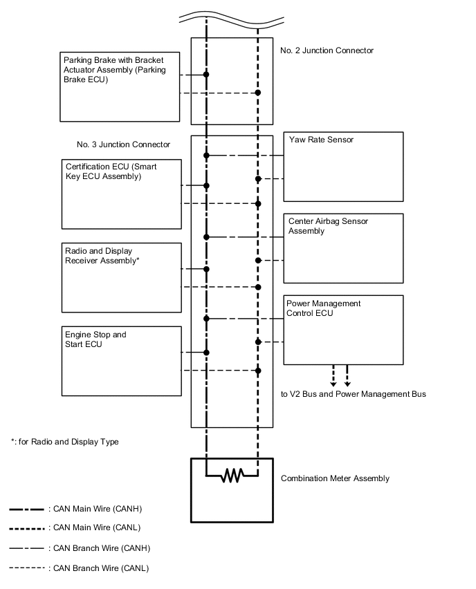
V2 Bus (w/ Entry and Start System)
-
MS Bus (w/ Seat Position Memory System, w/ Entry and Start System)
-
Power Management Bus