CHARGING SYSTEM TERMINALS OF ECU
-
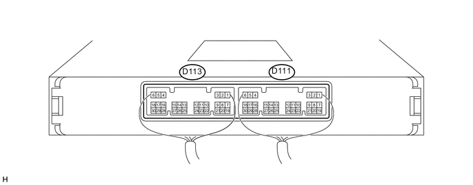
CHECK POWER MANAGEMENT CONTROL ECU (w/ Entry and Start System)
-
Measure the voltage and resistance according to the value(s) in the table below.
Tech Tips
Perform the measurements with the connectors connected.
Terminal No. (Symbol) Wiring Color Terminal Description Condition Specified Condition D111-1 (AM22) - Body ground W - Body ground Battery Always 11 to 14 V D111-2 (AM21) - Body ground W - Body ground Battery Always 11 to 14 V D111-6 (GND) - Body ground W-B - Body ground Ground Always Below 1 Ω D113-1 (LIN1) - Body ground V - Body ground LIN communication signal Ignition switch off (while LIN communication is stopped) 10 kΩ or higher D113-23 (VC) - D113-25 (E2) LG - BR Battery current sensor power supply Ignition switch ON 4.5 to 5.5 V D113-28 (THB) - D113-25 (E2) P - BR Battery current sensor thermistor signal Ignition switch ON
(Temperature of thermistor of battery current sensor: -30 to 90°C (-22 to 194°F))
0.5 to 4.5 V D113-30 (IB) - D113-25 (E2) B - BR Battery current sensor signal Ignition switch ON
(Temperature of thermistor of battery current sensor: -30 to 90°C (-22 to 194°F))
0.5 to 4.5 V D113-25 (E2) - Body ground BR - Body ground Battery current sensor ground Always Below 1 Ω If the result is not as specified, the ECU may have a malfunction.
-
-
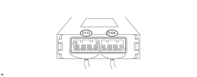
CHECK POWER MANAGEMENT CONTROL ECU (w/o Entry and Start System)
-
Measure the voltage and resistance according to the value(s) in the table below.
Tech Tips
Perform the measurements with the connectors connected.
Terminal No. (Symbol) Wiring Color Terminal Description Condition Specified Condition D104-8 (AM21) - Body ground W - Body ground Battery Always 11 to 14 V D104-12 (GND) - Body ground W-B - Body ground Ground Always Below 1 Ω D112-17 (LIN1) - Body ground V - Body ground LIN communication signal Ignition switch off (while LIN communication is stopped) 10 kΩ or higher D112-12 (VC) - D112-18 (E2) LG - BR Battery current sensor power supply Ignition switch ON 4.5 to 5.5 V D112-15 (THB) - D112-18 (E2) P - BR Battery current sensor thermistor signal Ignition switch ON
(Temperature of thermistor of battery current sensor: -30 to 90°C (-22 to 194°F))
0.5 to 4.5 V D112-13 (IB) - D112-18 (E2) B - BR Battery current sensor signal Ignition switch ON
(Temperature of thermistor of battery current sensor: -30 to 90°C (-22 to 194°F))
0.5 to 4.5 V D112-18 (E2) - Body ground BR - Body ground Battery current sensor ground Always Below 1 Ω If the result is not as specified, the ECU may have a malfunction.
-