REAR VIEW MONITOR SYSTEM(for Radio and Display Type) Image from Camera for Rear View Monitor is Abnormal
DESCRIPTION
This is the display signal circuit between the radio and display receiver assembly and the rear television camera assembly.
WIRING DIAGRAM
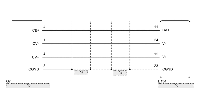
| *a | Shielded |
| *b | Rear Television Camera Assembly |
| *c | Radio and Display Receiver Assembly |
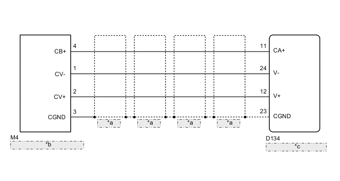
| *a | Shielded |
| *b | Rear Television Camera Assembly |
| *c | Radio and Display Receiver Assembly |
PROCEDURE
-
CHECK HARNESS AND CONNECTOR (RADIO AND DISPLAY RECEIVER ASSEMBLY - REAR TELEVISION CAMERA ASSEMBLY)
-
Disconnect the D134 radio and display receiver assembly connector.
-
Disconnect the G7*1 or M4*2 rear television camera assembly connector.
-
*1: for Sedan
-
*2: for Wagon
-
-
Measure the resistance according to the value(s) in the table below.
Standard Resistance for Sedan Tester Connection Condition Specified Condition D134-11 (CA+) - G7-4 (CB+) Always Below 1 Ω D134-12 (V+) - G7-2 (CV+) Always Below 1 Ω D134-23 (CGND) - G7-3 (CGND) Always Below 1 Ω D134-24 (V-) - G7-1 (CV-) Always Below 1 Ω D134-11 (CA+) - Body ground Always 10 kΩ or higher D134-12 (V+) - Body ground Always 10 kΩ or higher D134-23 (CGND) - Body ground Always 10 kΩ or higher D134-24 (V-) - Body ground Always 10 kΩ or higher for Wagon Tester Connection Condition Specified Condition D134-11 (CA+) - M4-4 (CB+) Always Below 1 Ω D134-12 (V+) - M4-2 (CV+) Always Below 1 Ω D134-23 (CGND) - M4-3 (CGND) Always Below 1 Ω D134-24 (V-) - M4-1 (CV-) Always Below 1 Ω D134-11 (CA+) - Body ground Always 10 kΩ or higher D134-12 (V+) - Body ground Always 10 kΩ or higher D134-23 (CGND) - Body ground Always 10 kΩ or higher D134-24 (V-) - Body ground Always 10 kΩ or higher
NG 
REPAIR OR REPLACE HARNESS OR CONNECTOR
OK 
-
-
CHECK RADIO AND DISPLAY RECEIVER ASSEMBLY
-
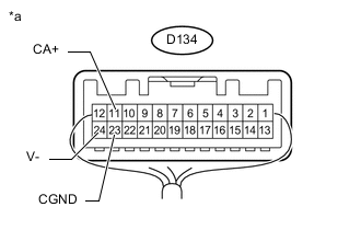
Text in Illustration *a Component with harness connected
(Radio and Display Receiver Assembly)
Measure the resistance according to the value(s) in the table below.
Standard Resistance Tester Connection Condition Specified Condition D134-23 (CGND) - Body ground Always Below 1 Ω D134-24 (V-) - Body ground Always Below 1 Ω -
Measure the voltage according to the value(s) in the table below.
Standard Voltage Tester Connection Switch Condition Specified Condition D134-11 (CA+) - Body ground Ignition switch ON 5.5 to 7.05 V
NG
REPLACE RADIO AND DISPLAY RECEIVER ASSEMBLY Click here
OK
-
-
CHECK REAR TELEVISION CAMERA ASSEMBLY
-
Using an oscilloscope, check the waveform.
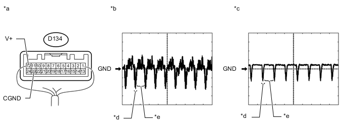
Text in Illustration *a Component with harness connected
(Radio and Display Receiver Assembly)
*b Waveform 1 *c Waveform 2 *d Synchronized Signal *e Video Waveform - - Measurement Condition Item Content Tester Connection D134-12 (V+) - D134-23 (CGND) Tool Setting 200 mV/DIV., 50 μs/DIV. Condition
-
Waveform 1: Ignition switch ON, camera lens not covered, displaying an image
-
Waveform 2: Ignition switch ON, camera lens covered, blacking out screen
OK Waveform is as shown in illustration. Tech Tips
The video waveform changes according to the image sent by the rear television camera assembly.
Result Result Proceed to OK A NG (for Sedan) B NG (for Wagon) C -
A
PROCEED TO NEXT SUSPECTED AREA SHOWN IN PROBLEM SYMPTOMS TABLE Click here
B
REPLACE REAR TELEVISION CAMERA ASSEMBLY Click here
C
REPLACE REAR TELEVISION CAMERA ASSEMBLY Click here
-