TOYOTA PARKING ASSIST-SENSOR SYSTEM Clearance Warning Buzzer Circuit
DESCRIPTION
The clearance warning buzzer sounds to alert the driver and the buzzed frequency changes depending on the distance to an obstacle.
WIRING DIAGRAM
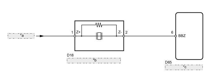
| *a | from ECU-IG NO. 3 Fuse |
| *b | No. 1 Clearance Warning Buzzer |
| *c | Clearance Warning ECU |
CAUTION / NOTICE / HINT
Note
Inspect the fuses for circuits related to this system before performing the following inspection procedure.
PROCEDURE
-
CHECK HARNESS AND CONNECTOR (NO. 1 CLEARANCE WARNING BUZZER - BATTERY)
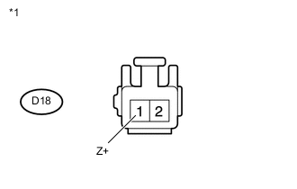
Text in Illustration *1 Front view of wire harness connector
(to No. 1 Clearance Warning Buzzer)
-
Disconnect the D18 buzzer connector.
-
Measure the voltage according to the value(s) in the table below.
Standard Voltage Tester Connection Switch Condition Specified Condition D18-1 (Z+) - Body ground Ignition switch ON 11 to 14 V D18-1 (Z+) - Body ground Ignition switch off Below 1 V
NG 
REPAIR OR REPLACE HARNESS OR CONNECTOR
OK 
-
-
CHECK HARNESS AND CONNECTOR (NO. 1 CLEARANCE WARNING BUZZER - CLEARANCE WARNING ECU)
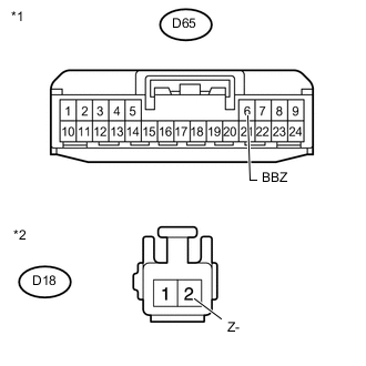
Text in Illustration *1 Front view of wire harness connector
(to Clearance Warning ECU)
*2 Front view of wire harness connector
(to No. 1 Clearance Warning Buzzer)
-
Disconnect the D65 ECU connector.
-
Disconnect the D18 buzzer connector.
-
Measure the resistance according to the value(s) in the table below.
Standard Resistance Tester Connection Condition Specified Condition D65-6 (BBZ) - D18-2 (Z-) Always Below 1 Ω D65-6 (BBZ) - Body ground Always 10 kΩ or higher
NG
REPAIR OR REPLACE HARNESS OR CONNECTOR
OK
-
-
REPLACE NO. 1 CLEARANCE WARNING BUZZER
-
Replace the No. 1 clearance warning buzzer with a normally functioning or new one Click here.
NEXT
-
-
CHECK NO. 1 CLEARANCE WARNING BUZZER
-
Check that the No. 1 clearance warning buzzer operates normally.
OK No. 1 clearance warning buzzer operates normally.
OK
END
NG
PROCEED TO NEXT SUSPECTED AREA SHOWN IN PROBLEM SYMPTOMS TABLE Click here
-