NAVIGATION SYSTEM TERMINALS OF ECU
-
RADIO AND DISPLAY RECEIVER ASSEMBLY
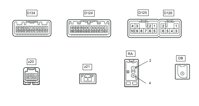
Terminal No. (Symbol) Wiring Color Terminal Description Condition Specified Condition D126-1 (RR+) - D125-7 (GND1) R - BR Sound signal (Right) Audio system playing A waveform synchronized with voice signals is output D126-2 (RL+) - D125-7 (GND1) B - BR Sound signal (Left) Audio system playing A waveform synchronized with voice signals is output D126-3 (RR-) - D125-7 (GND1) W - BR Sound signal (Right) Audio system playing A waveform synchronized with voice signals is output D126-6 (RL-) - D125-7 (GND1) Y - BR Sound signal (Left) Audio system playing A waveform synchronized with voice signals is output D125-1 (FR+) - D125-7 (GND1) LG - BR Sound signal (Right) Audio system playing A waveform synchronized with sound signals is output D125-2 (FL+) - D125-7 (GND1) P - BR Sound signal (Left) Audio system playing A waveform synchronized with sound signals is output D125-3 (ACC1) - D125-7 (GND1) GR - BR Power source (ACC) Ignition switch ACC 10.5 to 16 V Ignition switch off Below 1 V D125-4 (+B1) - D125-7 (GND1) SB - BR Power source Always 10.5 to 16 V D125-5 (FR-) - D125-7 (GND1) L - BR Sound signal (Right) Audio system playing A waveform synchronized with sound signals is output D125-6 (FL-) - D125-7 (GND1) V - BR Sound signal (Left) Audio system playing A waveform synchronized with sound signals is output D125-7 (GND1) - Body ground BR - Body ground Ground Always Below 1 Ω D125-9 (AMP) - D125-7 (GND1)*1 BR - BR Power source of stereo component amplifier Audio system playing 11 to 14 V D125-10 (ILL+) - D125-7 (GND1) G - BR Illumination signal Ignition switch ON, light control switch off → tail or head position Below 1 V → 11 to 14 V D124-1 (IG) - D125-7 (GND1) G - BR Power source (IG) Ignition switch ON 10.5 to 16 V Ignition switch off Below 1 V D124-4 (MACC) - D125-7 (GND1) B - BR Telephone microphone assembly power supply Ignition switch off Below 1 V Ignition switch ACC 4 to 6 V D124-5 (MIN+) - D125-7 (GND1) W - BR Microphone voice signal See "Microphone & Voice Recognition Check" in Operation Check Click here
- D124-6 (SNS2) - D125-7 (GND1) L - BR Microphone connection detection signal Always Below 1 V D124-9 (CANH) SB CAN communication signal - - D124-10 (CANL) W CAN communication signal - - D124-11 (AGND) - Body ground Shielded - Body ground Shield ground Always Below 1 V D124-17 (SPD) - D125-7 (GND1) Y - BR Speed signal from combination meter assembly See "Vehicle Signal Check Mode" in Operation Check Click here
- D124-18 (SGND) - D125-7 (GND1) Shielded - BR Shield ground Always Below 1 V D124-19 (MIN-) - Body ground R - Body ground Microphone voice signal See "Microphone & Voice Recognition Check" in Operation Check Click here
- D124-21 (SW1) - D124-23 (SWG) P - W-B Steering pad switch signal Steering pad switch not operated 4.44 to 5.43 V Seek+ switch pushed 0.45 to 0.65 V Seek- switch pushed 1.19 to 1.49 V Vol+ switch pushed 2.09 to 2.54 V Vol- switch pushed 3.2 to 3.88 V D124-22 (SW2) - D124-23 (SWG) SB - W-B Steering pad switch signal Steering pad switch not operated 4.44 to 5.43 V MODE switch pushed 0.45 to 0.65 V On hook switch pushed 1.19 to 1.49 V Off hook switch pushed 2.09 to 2.54 V Voice switch pushed 3.2 to 3.88 V D124-23 (SWG) - Body ground W-B - Body ground Steering pad switch signal Always Below 1 V D124-25 (ADPG) - D125-7 (GND1) L - BR External device connector detection signal External device connected Below 1 V External device not connected 2.1 to 3 V D124-26 (VAR+) - D124-27 (VA-) R - W Sound signal (Right) AUX audio device playing (When stereo jack adapter used) A waveform synchronized with voice signals is output D124-27 (VA-) - D125-7 (GND1) W - BR Sound signal ground Always Below 1 V D124-28 (VAL+) - D124-27 (VA-) B - W Sound signal (Left) AUX audio device playing (When stereo jack adapter used) A waveform synchronized with sound signals is output D134-3 (CNH1) P Local bus communication signal - - D134-4 (CNL1) V Local bus communication signal - - z20-1 (SLD4) - Body ground B - Body ground Shield ground Always Below 1 V z20-2 (SPDO) - D125-7 (GND1) B - BR Vehicle speed signal See "Check Vehicle Signal" in Operation Check Click here
- z20-3 (ACC2) - D125-7 (GND1) B - BR Power source (ACC) Ignition switch off Below 1 V Ignition switch ACC 11 to 14 V z20-4 (+B2) - D125-7 (GND1) W - BR Power source (+B) Always 11 to 14 V z20-5 (MIC+) - D125-7 (GND1) B - BR Microphone voice signal See "Microphone & Voice Recognition Check" in Operation Check Click here
- z20-6 (MIC-) - D125-7 (GND1) B - BR Microphone voice signal See "Microphone & Voice Recognition Check" in Operation Check Click here
- z20-8 (GND2) - Body ground W - Body ground Ground Always - z21-1 (LV) # LVDS communication signal - - DB-1 (DAB)*2 # DAB antenna - - RA-5 (ANT+) - Body ground # - Body ground Power source of antenna Ignition switch ACC
Radio switch on and AM or FM selected
11 to 14 V
-
*1: for 10 Speakers
-
*2: w/ DAB Function
-
#: There is no wire color information
-
-
NAVIGATION ECU
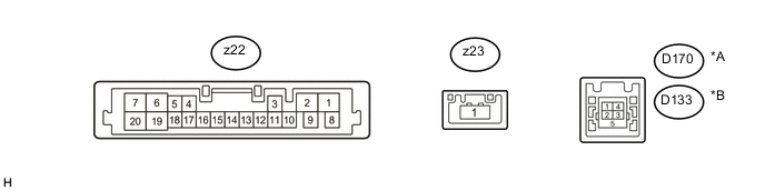
Text in Illustration *A for LHD *B for RHD Terminal No. (Symbol) Wiring Color Terminal Description Condition Specified Condition z22-1 (B+) - z22-2 (GND) W - W Power source (+B) Always 11 to 14 V z22-2 (GND) - Body ground W - Body ground Ground Always Below 1 V z22-3 (ACC) - z22-2 (GND) B - W Power source (ACC) Ignition switch off Below 1 V Ignition switch ACC 11 to 14 V z22-5 (SPD) - z22-2 (GND) B - W Vehicle speed signal Ignition switch ON Wheel being rotated Pulse generation z22-16 (MIC+) - z22-2 (GND) B - W Microphone voice signal See "Microphone & Voice Recognition Check" in Operation Check Click here
- z22-17 (MIC-) - z22-2 (GND) B - W Microphone voice signal See "Microphone & Voice Recognition Check" in Operation Check Click here
- z22-18 (MSHLD) - Body ground B - Body ground Shield ground Always Below 1 V D170-1 (USV1)*1
D133-1 (USV1)*2
# Power source - - D170-2 (US1-)*1
D133-2 (US1-)*2
# Data signal - - D170-3 (US1+)*1
D133-3 (US1+)*2
# Data signal - - D170-4 (UGD1)*1
D133-4 (UGD1)*2
# Ground - - D170-5 (USG1)*1
D133-5 (USG1)*2
Shielded Shield ground - - z23-1 (LV) # LVDS communication signal - -
-
*1: for LHD
-
*2: for RHD
-
#: There is no wire color information
-
-
STEREO COMPONENT AMPLIFIER ASSEMBLY (for 10 Speakers)

Terminal No. (Symbol) Wiring Color Terminal Description Condition Specified Condition H20-1 (RL+) - H20-10 (GND) P - W-B Sound signal (Front Left) Audio system playing A waveform synchronized with sound signals is output H20-2 (RR+) - H20-10 (GND) LG - W-B Sound signal (Front Right) Audio system playing A waveform synchronized with sound signals is output H20-3 (WFR+) - H20-10 (GND) LG - W-B Sound signal (Front Right) Audio system playing A waveform synchronized with sound signals is output H20-4 (WFL+) - H20-10 (GND) P - W-B Sound signal (Front Left) Audio system playing A waveform synchronized with sound signals is output H20-5 (+B) - H20-10 (GND) G - W-B Power source (+B) Always 11 to 14 V H20-6 (RL-) - H20-10 (GND) V - W-B Sound signal (Front Left) Audio system playing A waveform synchronized with sound signals is output H20-7 (RR-) - H20-10 (GND) L - W-B Sound signal (Front Right) Audio system playing A waveform synchronized with sound signals is output H20-8 (WFR-) - H20-10 (GND) L - W-B Sound signal (Front Right) Audio system playing A waveform synchronized with sound signals is output H20-9 (AMP+) - Body ground BR - Body ground Power source of stereo component amplifier Audio system playing 11 to 14 V H20-10 (GND) - Body ground W-B - Body ground Ground Always Below 1 Ω H20-11 (WFL-) - H20-10 (GND) V - W-B Sound signal (Front Left) Audio system playing A waveform synchronized with sound signals is output H20-12 (ACC) - H20-10 (GND) GR - W-B Power source (ACC) Ignition switch off Below 1 V Ignition switch ACC 11 to 14 V