INTEGRATION RELAY ON-VEHICLE INSPECTION
PROCEDURE
-
REMOVE NO. 1 RELAY BLOCK COVER
-
INSPECT INTEGRATION NO.1 RELAY
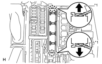
Text in Illustration *1 Protective Tape
-
Using a screwdriver, detach the 2 claws and disconnect the integration relay from the engine room junction block.
Tech Tips
Tape the screwdriver tip before use.
-
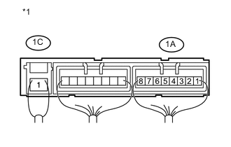
Text in Illustration *1 Component with harness connected
(Integration Relay)
Measure the resistance according to the value(s) in the table below.
Standard Resistance Tester Connection Condition Specified Condition 1A-8 - 1C-1 Battery voltage is not applied to terminals 1A-6 and 1A-7 10 kΩ or higher 1A-8 - 1A-5 1A-8 - 1C-1 Battery voltage is applied to terminals 1A-6 and 1A-7 Below 1 Ω 1A-8 - 1A-5 If the result is not as specified, replace the integration relay.
-
Attach the 2 claws to install the integration relay to the engine room junction block.
-
-
INSTALL NO. 1 RELAY BLOCK COVER