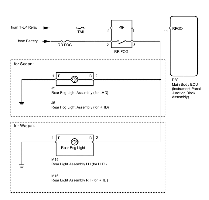
LIGHTING SYSTEM Rear Fog Light Circuit
DESCRIPTION
The main body ECU receives a rear fog light switch information signal from the light control switch (rear fog switch), and illuminates the rear fog lights.
WIRING DIAGRAM
CAUTION / NOTICE / HINT
Tech Tips
Inspect the fuses and bulbs for circuits related to this system before performing the following inspection procedure.
PROCEDURE
-
PERFORM ACTIVE TEST USING INTELLIGENT TESTER (REAR FOG LIGHT)
-
Connect the intelligent tester to the DLC3.
-
Turn the ignition switch to ON.
-
Turn the intelligent tester on.
-
Enter the following menus: Body / Main Body / Active Test / Rear Fog Light.
-
Check that the rear fog lights turn on/off.
Main Body Tester Display Test Part Control Range Diagnostic Note Rear Fog Light Relay Rear fog light ON or OFF - OK Rear fog lights turn on/off.
OK 
REPLACE MAIN BODY ECU (INSTRUMENT PANEL JUNCTION BLOCK ASSEMBLY)
NG 
-
-
CHECK HARNESS AND CONNECTOR (REAR FOG LIGHT - BATTERY)
-
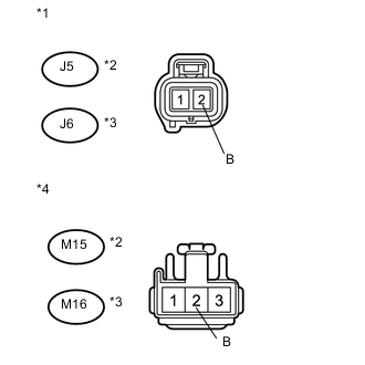
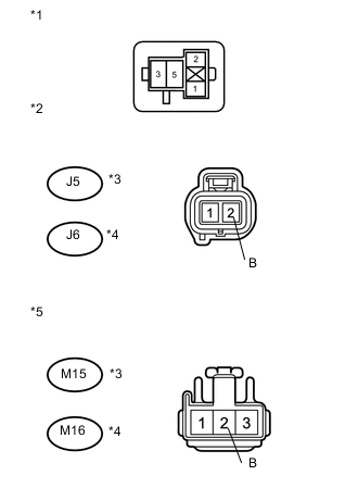
Text in Illustration *1 Front view of wire harness connector
(to Rear Fog Light [for Sedan])
*2 for LHD *3 for RHD *4 Front view of wire harness connector
(to Rear Light [for Wagon])
for Sedan:
-
Disconnect the J5 or J6 rear fog light connector.
-
Measure the voltage according to the value(s) in the table below.
Standard Voltage for LHD Tester Connection Switch Condition Specified Condition J5-2 (B) - Body ground Light control switch TAIL, rear fog light switch on 11 to 14 V Light control switch TAIL, rear fog light switch off Below 1 V for RHD Tester Connection Switch Condition Specified Condition J6-2 (B) - Body ground Light control switch TAIL, rear fog light switch on 11 to 14 V Light control switch TAIL, rear fog light switch off Below 1 V
-
-
for Wagon:
-
Disconnect the M15 or M16 rear light connector.
-
Measure the voltage according to the value(s) in the table below.
Standard Voltage for LHD Tester Connection Switch Condition Specified Condition M15-2 (B) - Body ground Light control switch TAIL, rear fog light switch on 11 to 14 V Light control switch TAIL, rear fog light switch off Below 1 V for RHD Tester Connection Switch Condition Specified Condition M16-2 (B) - Body ground Light control switch TAIL, rear fog light switch on 11 to 14 V Light control switch TAIL, rear fog light switch off Below 1 V
-
OK
REPAIR OR REPLACE HARNESS OR CONNECTOR (REAR FOG LIGHT - BODY GROUND)
NG
-
-
INSPECT REAR FOG LIGHT RELAY (RR FOG)
-
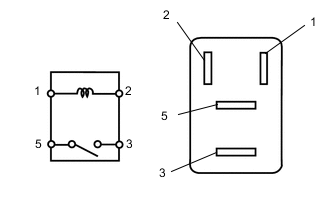
Remove the rear fog light relay from the No. 1 relay block.
-
Measure the resistance according to the value(s) in the table below.
Standard Voltage Tester Connection Switch Condition Specified Condition 3 - 5 Battery voltage not applied to terminals 1 and 2 10 Ω or higher Battery voltage applied to terminals 1 and 2 Below 1 Ω
NG
REPLACE REAR FOG LIGHT RELAY
OK
-
-
CHECK HARNESS AND CONNECTOR (REAR FOG LIGHT RELAY - BATTERY AND TAIL RELAY)
-
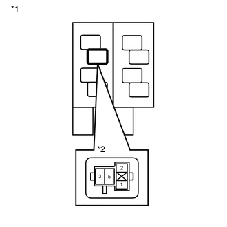
Text in Illustration *1 Component without relay connected
(No. 1 Relay Block)
*2 Rear Fog Light Relay (RR FOG) Remove the rear fog light relay from the No. 1 relay block.
-
Measure the voltage according to the value(s) in the table below.
Standard Voltage Tester Connection Switch Condition Specified Condition Rear fog light relay terminal 2 - Body ground Light control switch TAIL 11 to 14 V Rear fog light relay terminal 5 - Body ground Always 11 to 14 V
NG
REPAIR OR REPLACE HARNESS OR CONNECTOR
OK
-
-
CHECK HARNESS AND CONNECTOR (REAR FOG LIGHT RELAY - REAR FOG LIGHT)
-
Text in Illustration *1 Component without relay connected
(No. 1 Relay Block)
*2 Front view of wire harness connector
(to Rear Fog Light [for Sedan])
*3 for LHD *4 for RHD *5 Front view of wire harness connector
(to Rear Light [for Wagon])
Remove the rear fog light relay from the No. 1 relay block.
-
for Sedan:
-
Disconnect the J5 or J6 rear fog light connector.
-
Measure the resistance according to the value(s) in the table below.
Standard Resistance for LHD Tester Connection Condition Specified Condition Rear fog light relay terminal 3 - J5-2 (B) Always Below 1 Ω Rear fog light relay terminal 3 - Body ground Always 10 Ω or higher for RHD Tester Connection Condition Specified Condition Rear fog light relay terminal 3 - J6-2 (B) Always Below 1 Ω Rear fog light relay terminal 3 - Body ground Always 10 Ω or higher
-
-
for Wagon:
-
Disconnect the M15 or M16 rear light connector.
-
Measure the resistance according to the value(s) in the table below.
Standard Resistance for LHD Tester Connection Condition Specified Condition Rear fog light relay terminal 3 - M15-2 (B) Always Below 1 Ω Rear fog light relay terminal 3 - Body ground Always 10 Ω or higher for RHD Tester Connection Condition Specified Condition Rear fog light relay terminal 3 - M16-2 (B) Always Below 1 Ω Rear fog light relay terminal 3 - Body ground Always 10 Ω or higher
-
NG
REPAIR OR REPLACE HARNESS OR CONNECTOR
OK
-
-
CHECK HARNESS AND CONNECTOR (REAR FOG LIGHT RELAY - MAIN BODY ECU)
-
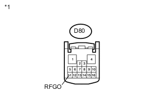
Text in Illustration *1 Front view of wire harness connector
(to Main Body ECU)
Disconnect the D80 main body ECU connector.
-
Measure the voltage according to the value(s) in the table below.
Standard Voltage Tester Connection Switch Condition Specified Condition D80-11 (RFGO) - Body ground Light control switch TAIL 11 to 14 V
OK
PROCEED TO NEXT SUSPECTED AREA SHOWN IN PROBLEM SYMPTOMS TABLE Click here
NG
REPAIR OR REPLACE HARNESS OR CONNECTOR
-