LIGHTING SYSTEM, Diagnostic DTC:B2416, B241A

| DTC Code | DTC Name |
|---|---|
| B2416 | Height Control Sensor Malfunction |
| B241A | Rear Height Control Sensor |
DESCRIPTION
The headlight swivel ECU assembly*1 or headlight leveling ECU assembly*2 receives signals indicating the height of the vehicle from the rear height control sensor sub-assembly.
-
*1: w/ AFS
-
*2: w/o AFS
| DTC Code | DTC Detection Condition | Trouble Area |
|---|---|---|
| B2416 | Either condition is met:
|
|
| B241A | Either condition is met:
|
|
WIRING DIAGRAM
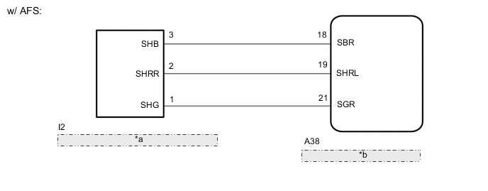
| *a | Rear Height Control Sensor Sub-assembly |
| *b | Headlight Swivel ECU Assembly |
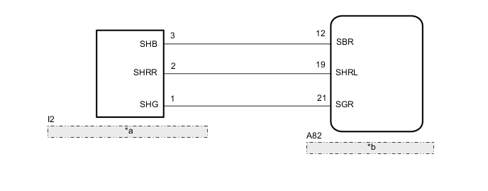
| *a | Rear Height Control Sensor Sub-assembly |
| *b | Headlight Leveling ECU Assembly |
CAUTION / NOTICE / HINT
Tech Tips
After replacing the headlight swivel ECU assembly*1 or headlight leveling ECU assembly*2, initialization of the ECU is necessary Click here.
-
*1: w/ AFS
-
*2: w/o AFS
PROCEDURE
-
CHECK FOR DTC
-
Clear the DTCs Click here.
-
Check for DTCs Click here.
OK DTC B2416 output does not occur. Result Result Proceed to OK A NG (w/ AFS) B NG (w/o AFS) C
A 
USE SIMULATION METHOD TO CHECK Click here
C 
READ VALUE USING GTS Click here
B 
-
-
READ VALUE USING GTS
-
Connect the GTS to the DLC3.
-
Turn the ignition switch to ON.
-
Turn the GTS on.
-
Enter the following menus: Body / AFS / Data List.
-
Using the GTS, read the Data List.
AFS Tester Display Measurement Item/Range Normal Condition Diagnostic Note Height Sens Pw Supply Val Rear height control sensor power supply value / Min.: 0 V, Max.: 5 V Approximately 5 V w/ AFS Rr Height Sens Signal Val Rear height control sensor signal / Min.: 0 V, Max.: 5 V Changes according to vehicle height w/ AFS OK Power supply voltage is approximately 5 V and height control sensor signal voltage changes when vehicle height is changed.
OK
REPLACE HEADLIGHT SWIVEL ECU ASSEMBLY Click here
NG
-
-
CHECK HARNESS AND CONNECTOR (HEADLIGHT SWIVEL ECU ASSEMBLY - REAR HEIGHT CONTROL SENSOR SUB-ASSEMBLY)
-
Disconnect the A38 headlight swivel ECU assembly connector
-
Disconnect the I2 rear height control sensor sub-assembly connector.
-
Measure the resistance according to the value(s) in the table below.
Standard Resistance Tester Connection Condition Specified Condition A38-18 (SBR) - I2-3 (SHB) Always Below 1 Ω A38-19 (SHRL) - I2-2 (SHRR) A38-21 (SGR) - I2-1 (SHG) A38-18 (B) - Body ground Always 10 kΩ or higher A38-19 (SHRL) - Body ground A38-21 (SGR) - Body ground
OK
REPLACE REAR HEIGHT CONTROL SENSOR SUB-ASSEMBLY Click here
NG
REPAIR OR REPLACE HARNESS OR CONNECTOR
-
-
READ VALUE USING GTS
-
Connect the GTS to the DLC3.
-
Turn the ignition switch to ON.
-
Turn the GTS on.
-
Enter the following menus: Body / HL AutoLeveling / Data List.
-
Using the GTS, read the Data List.
HL AutoLeveling Tester Display Measurement Item/Range Normal Condition Diagnostic Note Height Sens Pw Supply Val Rear height control sensor power supply value / 0 to 5 V Approximately 5.0 V
-
The value changes according to the vehicle height.
-
w/o AFS
Rear Height Adjust Value Rear height adjustment offset value / 0 to 1023 Actual rear height adjustment normal value is displayed (If there is a malfunction, no value is displayed) w/o AFS Rear Height Adjust Valid Flag Result of rear vehicle height calibration / Valid or Inval Valid: Rear vehicle height calibration completed
Inval: Rear vehicle height calibration not completed
w/o AFS OK Power supply voltage is approximately 5 V and height control sensor signal voltage changes when vehicle height is changed. Result Result Proceed to OK (for LHD) A OK (for RHD) B NG C -
A
REPLACE HEADLIGHT LEVELING ECU ASSEMBLY Click here
B
REPLACE HEADLIGHT LEVELING ECU ASSEMBLY Click here
C
-
-
CHECK HARNESS AND CONNECTOR (HEADLIGHT LEVELING ECU ASSEMBLY - REAR HEIGHT CONTROL SENSOR SUB-ASSEMBLY)
-
Disconnect the A82 headlight leveling ECU assembly connector.
-
Disconnect the I2 rear height control sensor sub-assembly connector.
-
Measure the resistance according to the value(s) in the table below.
Standard Resistance Tester Connection Condition Specified Condition A82-12 (SBR) - I2-3 (SHB) Always Below 1 Ω A82-19 (SHRL) - I2-2 (SHRR) A82-21 (SGR) - I2-1 (SHG) A82-18 (B) - Body ground Always 10 kΩ or higher A82-19 (SHRL) - Body ground A82-21 (SGR) - Body ground
OK
REPLACE REAR HEIGHT CONTROL SENSOR SUB-ASSEMBLY Click here
NG
REPAIR OR REPLACE HARNESS OR CONNECTOR
-