REAR SUSPENSION MEMBER REMOVAL

PROCEDURE
-
PRECAUTION
Note
After turning the ignition switch off, waiting time may be required before disconnecting the cable from the battery terminal. Therefore, make sure to read the disconnecting the cable from the battery terminal notice before proceeding with work Click here.
-
DISCONNECT CABLE FROM NEGATIVE BATTERY TERMINAL
Note
When disconnecting the cable, some systems need to be initialized after the cable is reconnected Click here.
-
REMOVE REAR WHEEL
-
REMOVE TAILPIPE ASSEMBLY
-
for 1WW:
Remove the tailpipe assembly Click here.
-
for 2WW:
Remove the tailpipe assembly Click here.
-
-
DISCONNECT SKID CONTROL SENSOR WIRE
-
REMOVE FLOOR NO. 2 UNDER COVER
-
Remove the 6 clips and under cover.
-
-
DISCONNECT PARKING BRAKE CABLE AND EMERGENCY RELEASE CABLE
-
DISCONNECT REAR DISC BRAKE CALIPER ASSEMBLY LH
-
DISCONNECT REAR DISC BRAKE CALIPER ASSEMBLY RH
Tech Tips
Use the same procedure described for the LH side.
-
REMOVE REAR DISC
-
REMOVE REAR AXLE HUB AND BEARING ASSEMBLY LH
-
REMOVE REAR AXLE HUB AND BEARING ASSEMBLY RH
Tech Tips
Use the same procedure described for the LH side.
-
REMOVE REAR HEIGHT CONTROL SENSOR SUB-ASSEMBLY (for LED Headlight)
-
REMOVE REAR SUSPENSION ARM COVER LH
-
REMOVE REAR SUSPENSION ARM COVER RH
Tech Tips
Use the same procedure described for the LH side.
-
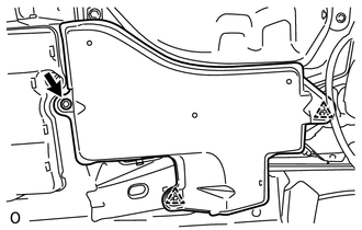
REMOVE REAR FLOOR SIDE MEMBER COVER RH
-
Detach the 2 clips, and remove the bolt and rear floor side member cover.
-
-
REMOVE REAR SUSPENSION MEMBER BRACE LH
-
REMOVE REAR SUSPENSION MEMBER BRACE RH
Tech Tips
Use the same procedure described for the LH side.
-
REMOVE REAR STABILIZER LINK ASSEMBLY LH
-
REMOVE REAR STABILIZER LINK ASSEMBLY RH
Tech Tips
Use the same procedure described for the LH side.
-
REMOVE REAR STABILIZER BAR
-
REMOVE REAR NO. 1 SUSPENSION ARM ASSEMBLY LH
-
REMOVE REAR NO. 1 SUSPENSION ARM ASSEMBLY RH
Tech Tips
Use the same procedures described for the LH side.
-
DISCONNECT REAR TRAILING ARM ASSEMBLY LH
-
Remove the 2 bolts and disconnect the rear trailing arm.
-
-
DISCONNECT REAR TRAILING ARM ASSEMBLY RH
Tech Tips
Use the same procedure described for the LH side.
-
LOOSEN REAR NO. 2 SUSPENSION ARM ASSEMBLY LH
-
LOOSEN REAR NO. 2 SUSPENSION ARM ASSEMBLY RH
Tech Tips
Use the same procedures described for the LH side.
-
REMOVE REAR AXLE CARRIER SUB-ASSEMBLY LH
-
Remove the bolt and nut, disconnect the rear upper control arm and remove the rear axle carrier.
Note
Since a stopper nut is used, loosen the bolt.
-
-
REMOVE REAR AXLE CARRIER SUB-ASSEMBLY RH
Tech Tips
Use the same procedure described for the LH side.
-
DISCONNECT REAR SHOCK ABSORBER ASSEMBLY LH
-
DISCONNECT REAR SHOCK ABSORBER ASSEMBLY RH
Tech Tips
Use the same procedure described for the LH side.
-
REMOVE REAR COIL SPRING LH
-
REMOVE REAR COIL SPRING RH
Tech Tips
Use the same procedure described for the LH side.
-
REMOVE REAR UPPER COIL SPRING INSULATOR LH
-
REMOVE REAR UPPER COIL SPRING INSULATOR RH
Tech Tips
Use the same procedure described for the LH side.
-
REMOVE REAR LOWER COIL SPRING INSULATOR LH
-
REMOVE REAR LOWER COIL SPRING INSULATOR RH
-
REMOVE REAR NO. 2 SUSPENSION ARM ASSEMBLY LH
-
REMOVE REAR NO. 2 SUSPENSION ARM ASSEMBLY RH
Tech Tips
Use the same procedure described for the LH side.
-
REMOVE REAR UPPER CONTROL ARM ASSEMBLY LH

-
Remove the bolt, nut and upper control arm from the rear suspension member.
-
-
REMOVE REAR UPPER CONTROL ARM ASSEMBLY RH
Tech Tips
Use the same procedure described for the LH side.
-
REMOVE REAR SUSPENSION MEMBER SUB-ASSEMBLY
CAUTION:
As the rear suspension member is very heavy, support it with an engine lift and attachments.
-
Support the rear suspension member with an engine lift and attachments.
-
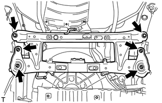
Remove the 2 bolts and 4 nuts.
-
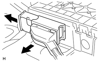
Slightly lower the rear suspension member, and then pull out the lock lever and disconnect the electric parking brake actuator connector.
-
Lower the rear suspension member sub-assembly.
-
-
REMOVE PARKING BRAKE WITH CABLE ACTUATOR ASSEMBLY
-
REMOVE PARKING BRAKE ACTUATOR SUPPORT BRACKET
-
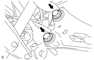
REMOVE REAR SUSPENSION MEMBER FRONT BODY MOUNTING CUSHION (w/o Rough Road Package 2)
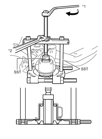
Text in Illustration *1 Turn *2 Hold
-
Using SST, remove the rear suspension member front body mounting cushion from the rear suspension member.
- SST
- 09950-00020
- 09950-00030
- 09950-40011 ( 09957-04010 )
- 09950-60010 ( 09951-00300 )
Note
The rear suspension member front body mounting cushion cannot be reused.
-
-
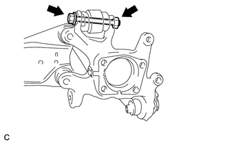
REMOVE REAR SUSPENSION MEMBER REAR BODY MOUNT CUSHION (w/o Rough Road Package 2)
Text in Illustration *1 Turn *2 Hold
-
Using SST, remove the cushion from the rear suspension member.
- SST
- 09950-00020
- 09950-00030 ( 09957-04010 )
- 09950-60010 ( 09951-00300 )
Note
The cushion cannot be reused.
-
-
REMOVE REAR SUSPENSION MEMBER DYNAMIC DAMPER
-
Remove the 4 bolts and 2 dynamic dampers from the rear suspension member.
-