REAR SUSPENSION MEMBER REMOVAL

PROCEDURE
-
DISCONNECT CABLE FROM NEGATIVE BATTERY TERMINAL
CAUTION:
Wait at least 90 seconds after disconnecting the cable from the negative (-) battery terminal to disable the SRS system.
Note
-
w/ Navigation System for HDD:
After the ignition switch is turned off, the HDD navigation system requires approximately a minute to record various types of memory and settings. As a result, after turning the ignition switch off, wait a minute or more before disconnecting the cable from the negative (-) battery terminal.
-
When disconnecting the cable, some systems need to be initialized after the cable is reconnected Click here.
-
-
REMOVE REAR WHEEL
-
REMOVE TAILPIPE ASSEMBLY
-
for 1AD-FTV:
Remove the tailpipe assembly Click here.
-
for 2AD-FTV:
Remove the tailpipe assembly Click here.
-
for 2AD-FHV:
Remove the tailpipe assembly Click here.
-
-
DISCONNECT SKID CONTROL SENSOR WIRE
-
REMOVE FLOOR NO. 2 UNDER COVER
-
Remove the 6 clips and under cover.
-
-
DISCONNECT PARKING BRAKE CABLE AND EMERGENCY RELEASE CABLE
-
DISCONNECT REAR DISC BRAKE CALIPER ASSEMBLY LH
-
DISCONNECT REAR DISC BRAKE CALIPER ASSEMBLY RH
Tech Tips
Use the same procedure described for the LH side.
-
REMOVE REAR DISC
-
REMOVE REAR AXLE HUB AND BEARING ASSEMBLY LH
-
REMOVE REAR AXLE HUB AND BEARING ASSEMBLY RH
Tech Tips
Use the same procedure described for the LH side.
-
REMOVE REAR HEIGHT CONTROL SENSOR SUB-ASSEMBLY (for HID Headlight)
-
REMOVE REAR SUSPENSION ARM COVER LH
-
REMOVE REAR SUSPENSION ARM COVER RH
Tech Tips
Use the same procedure described for the LH side.
-
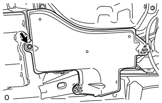
REMOVE REAR FLOOR SIDE MEMBER COVER RH
-
Detach the 2 clips, and remove the bolt and rear floor side member cover.
-
-
REMOVE REAR SUSPENSION MEMBER BRACE LH
-
REMOVE REAR SUSPENSION MEMBER BRACE RH
Tech Tips
Use the same procedure described for the LH side.
-
REMOVE REAR STABILIZER LINK ASSEMBLY LH
-
REMOVE REAR STABILIZER LINK ASSEMBLY RH
Tech Tips
Use the same procedure described for the LH side.
-
REMOVE REAR STABILIZER BAR
-
REMOVE REAR NO. 1 SUSPENSION ARM ASSEMBLY LH
-
REMOVE REAR NO. 1 SUSPENSION ARM ASSEMBLY RH
Tech Tips
Use the same procedures described for the LH side.
-
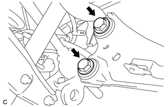
DISCONNECT REAR TRAILING ARM ASSEMBLY LH
-
Remove the 2 bolts and disconnect the rear trailing arm.
-
-
DISCONNECT REAR TRAILING ARM ASSEMBLY RH
Tech Tips
Use the same procedure described for the LH side.
-
LOOSEN REAR NO. 2 SUSPENSION ARM ASSEMBLY LH
-
LOOSEN REAR NO. 2 SUSPENSION ARM ASSEMBLY RH
Tech Tips
Use the same procedures described for the LH side.
-
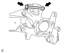
REMOVE REAR AXLE CARRIER SUB-ASSEMBLY LH
-
Remove the bolt and nut, disconnect the rear upper control arm and remove the rear axle carrier.
Note
Since a stopper nut is used, loosen the bolt.
-
-
REMOVE REAR AXLE CARRIER SUB-ASSEMBLY RH
Tech Tips
Use the same procedure described for the LH side.
-
DISCONNECT REAR SHOCK ABSORBER ASSEMBLY LH
-
DISCONNECT REAR SHOCK ABSORBER ASSEMBLY RH
Tech Tips
Use the same procedure described for the LH side.
-
REMOVE REAR COIL SPRING LH
-
REMOVE REAR COIL SPRING RH
Tech Tips
Use the same procedure described for the LH side.
-
REMOVE REAR UPPER COIL SPRING INSULATOR LH
-
REMOVE REAR UPPER COIL SPRING INSULATOR RH
Tech Tips
Use the same procedure described for the LH side.
-
REMOVE REAR LOWER COIL SPRING INSULATOR LH
-
REMOVE REAR LOWER COIL SPRING INSULATOR RH
-
REMOVE REAR NO. 2 SUSPENSION ARM ASSEMBLY LH
-
REMOVE REAR NO. 2 SUSPENSION ARM ASSEMBLY RH
Tech Tips
Use the same procedure described for the LH side.
-
REMOVE REAR UPPER CONTROL ARM ASSEMBLY LH

-
Remove the bolt, nut and upper control arm from the rear suspension member.
-
-
REMOVE REAR UPPER CONTROL ARM ASSEMBLY RH
Tech Tips
Use the same procedure described for the LH side.
-
REMOVE REAR SUSPENSION MEMBER SUB-ASSEMBLY
CAUTION:
As the rear suspension member is very heavy, support it with an engine lift and attachments.
-
Support the rear suspension member with an engine lift and attachments.
-
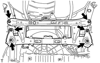
Remove the 2 bolts and 4 nuts.
-
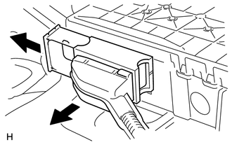
Slightly lower the rear suspension member, and then pull out the lock lever and disconnect the electric parking brake actuator connector.
-
Lower the rear suspension member sub-assembly.
-
-
REMOVE PARKING BRAKE WITH CABLE ACTUATOR ASSEMBLY
-
REMOVE PARKING BRAKE ACTUATOR SUPPORT BRACKET
-
REMOVE REAR SUSPENSION MEMBER FRONT BODY MOUNTING CUSHION (w/o Rough Road Package 2)
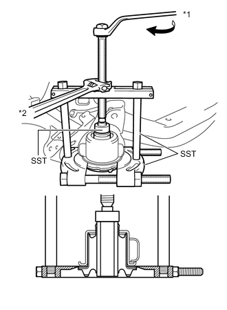
Text in Illustration *1 Turn *2 Hold
-
Using SST, remove the rear suspension member front body mounting cushion from the rear suspension member.
- SST
- 09950-00020
- 09950-00030
- 09950-40011 ( 09957-04010 )
- 09950-60010 ( 09951-00300 )
Note
The rear suspension member front body mounting cushion cannot be reused.
-
-
REMOVE REAR SUSPENSION MEMBER REAR BODY MOUNT CUSHION (w/o Rough Road Package 2)
Text in Illustration *1 Turn *2 Hold
-
Using SST, remove the cushion from the rear suspension member.
- SST
- 09950-00020
- 09950-00030 ( 09957-04010 )
- 09950-60010 ( 09951-00300 )
Note
The cushion cannot be reused.
-
-
REMOVE REAR SUSPENSION MEMBER DYNAMIC DAMPER
-
Remove the 4 bolts and 2 dynamic dampers from the rear suspension member.
-