FRONT STABILIZER BAR INSTALLATION
PROCEDURE
-
INSTALL FRONT NO. 1 STABILIZER BAR BUSHING (for LH Side)
-
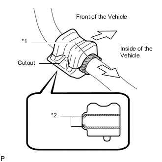
Text in Illustration *1 Stopper *2 Dust Lip Install the front No. 1 stabilizer bar bushing to the front stabilizer bar as shown in the illustration.
Note
-
Install the front No. 1 stabilizer bar bushing so that the dust lips face the outside of the vehicle.
-
Install the front No. 1 stabilizer bar bushing so that the cutout faces the rear of the vehicle.
-
-
-
INSTALL FRONT NO. 1 STABILIZER BAR BUSHING (for RH Side)
Tech Tips
Perform the same procedure as for the LH side.
-
INSTALL FRONT STABILIZER BAR
-
Install the front stabilizer bar to the front suspension crossmember so that the identification mark is positioned on the right side of the vehicle.
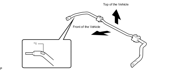
Text in Illustration *1 Identification Mark
-
-
INSTALL FRONT SUSPENSION MEMBER FRONT BRACE LH
-
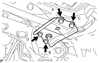
Text in Illustration *1 Protrusion Install the front brace with the 4 bolts.
- Torque:
- 92 N*m { 938 kgf*cm, 68 ft.*lbf }
Note
-
Tighten the bolts in the order of B, C, D and A.
-
Make sure that the protrusion of the No. 1 front stabilizer bar bushing protrudes from the hole of the front suspension member front brace LH when installing the front suspension member front brace LH.
-
-
INSTALL FRONT SUSPENSION MEMBER FRONT BRACE RH
-
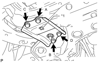
Text in Illustration *1 Protrusion Install the front brace with the 4 bolts.
- Torque:
- 92 N*m { 938 kgf*cm, 68 ft.*lbf }
Note
-
Tighten the bolts in the order of B, C, D and A.
-
Make sure that the protrusion of the No. 1 front stabilizer bar bushing protrudes from the hole of the front suspension member front brace RH when installing the front suspension member front brace RH.
-
-
TEMPORARILY INSTALL FRONT NO. 1 LOWER SUSPENSION ARM SUB-ASSEMBLY LH
-
INSTALL FRONT SUSPENSION CROSSMEMBER SUB-ASSEMBLY
-
INSTALL FRONT SUSPENSION MEMBER REAR BRACE LH
-
INSTALL FRONT SUSPENSION MEMBER REAR BRACE RH
-
INSTALL FRONT SUSPENSION MEMBER REINFORCEMENT LH
-
INSTALL FRONT SUSPENSION MEMBER REINFORCEMENT RH
-
CONNECT FRONT NO. 1 LOWER SUSPENSION ARM SUB-ASSEMBLY LH
-
CONNECT FRONT NO. 1 LOWER SUSPENSION ARM SUB-ASSEMBLY RH
Tech Tips
Perform the same procedure as for the LH side.
-
CONNECT TIE ROD END SUB-ASSEMBLY LH
-
CONNECT TIE ROD END SUB-ASSEMBLY RH
Tech Tips
Perform the same procedure as for the LH side.
-
CONNECT FRONT STABILIZER LINK ASSEMBLY LH
-
CONNECT FRONT STABILIZER LINK ASSEMBLY RH
Tech Tips
Perform the same procedure as for the LH side.
-
INSTALL NO. 1 STEERING COLUMN HOLE COVER SUB-ASSEMBLY
-
CONNECT NO. 2 STEERING INTERMEDIATE SHAFT ASSEMBLY
-
INSTALL COLUMN HOLE COVER SILENCER SHEET
-
INSTALL REAR ENGINE UNDER COVER LH
-
INSTALL REAR ENGINE UNDER COVER RH
Tech Tips
Perform the same procedure as for the LH side.
-
INSTALL FRONT WHEELS
- Torque:
- 103 N*m { 1050 kgf*cm, 76 ft.*lbf }
-
STABILIZE SUSPENSION
-
TIGHTEN FRONT NO. 1 LOWER SUSPENSION ARM SUB-ASSEMBLY LH
-
INSTALL NO. 4 CENTER ENGINE UNDER COVER
-
INSTALL NO. 1 ENGINE UNDER COVER
-
INSTALL FRONT LOWER BUMPER ABSORBER
-
INSPECT AND ADJUST FRONT WHEEL ALIGNMENT
-
Inspect and adjust the front wheel alignment Click here.
-