REAR LOWER ARM REMOVAL

PROCEDURE
-
PRECAUTION
Note
After turning the ignition switch off, waiting time may be required before disconnecting the cable from the battery terminal. Therefore, make sure to read the disconnecting the cable from the battery terminal notice before proceeding with work Click here.
-
DISCONNECT CABLE FROM NEGATIVE BATTERY TERMINAL
Note
When disconnecting the cable, some systems need to be initialized after the cable is reconnected Click here.
-
REMOVE REAR WHEEL
-
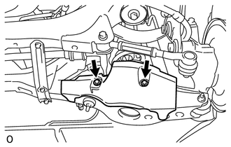
REMOVE REAR SUSPENSION ARM COVER LH
-
Remove the 2 bolts and cover.
-
-
REMOVE REAR NO. 1 SUSPENSION ARM ASSEMBLY LH
-
Turnbuckle Type:
-
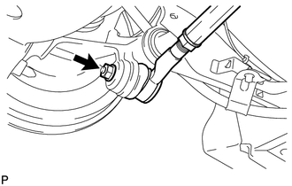
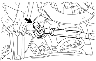
Remove the nut from the axle carrier.
-
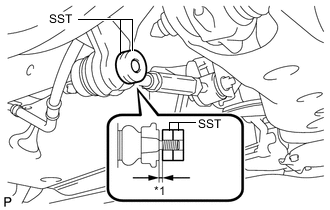
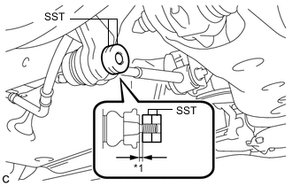
Text in Illustration *1 1 mm Install SST to the rear No. 1 suspension arm as shown in the illustration.
- SST
- 09960-20010 ( 09961-02060 )
Note
Make sure that the clearance measurement between SST and the rear axle assembly is 1 mm (0.0394 in.).
Tech Tips
Use 2 SST of the same type.
-
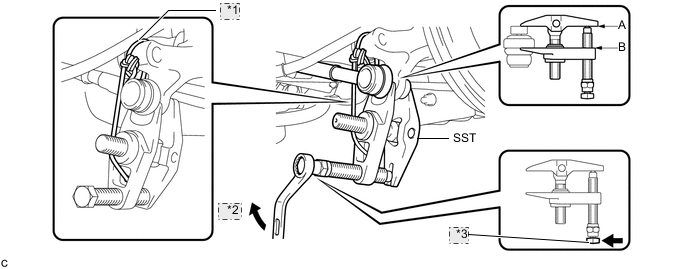
Using SST, disconnect the rear No. 1 suspension arm from the rear axle carrier as shown in the illustration.
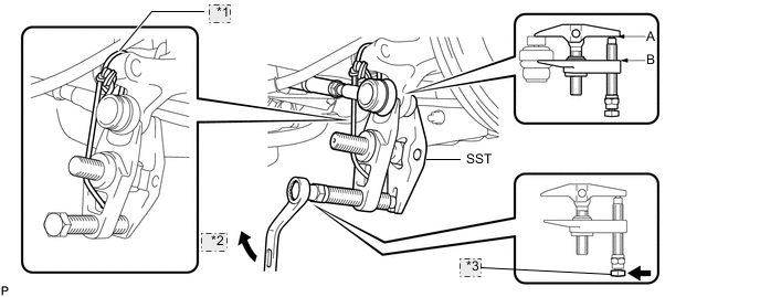
*1 Tie the string without allowing for slack. *2 Turn *3 Place the wrench here. - SST
- 09960-20010 ( 09961-02010 )
Note
-
Apply grease to the bolt threads and tip of SST.
-
Install SST so that A and B are parallel.
-
Be sure to turn the part indicated in the illustration with a wrench.
-
Do not damage the front lower ball joint dust cover.
-
Be sure to tie the string of SST to the vehicle to prevent SST from dropping.
-
Remove the bolt, nut and the rear No. 1 suspension arm.
Note
Since a stopper nut is used, loosen the bolt.
-
-
for Cam Type:
-
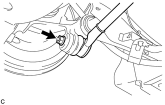
Remove the nut from the axle carrier.
-
Text in Illustration *1 1 mm Install SST to the rear No. 1 suspension arm as shown in the illustration.
- SST
- 09960-20010 ( 09961-02060 )
Note
Make sure that the clearance measurement between SST and the rear axle assembly is 1 mm (0.0394 in.).
Tech Tips
Use 2 SST of the same type.
-
Using SST, disconnect the rear No. 1 suspension arm from the rear axle carrier as shown in the illustration.
*1 Tie the string without allowing for slack. *2 Turn *3 Place the wrench here. - SST
- 09960-20010 ( 09961-02010 )
Note
-
Apply grease to the bolt threads and tip of SST.
-
Install SST so that A and B are parallel.
-
Be sure to turn the part indicated in the illustration with a wrench.
-
Do not damage the front lower ball joint dust cover.
-
Be sure to tie the string of SST to the vehicle to prevent SST from dropping.
-
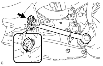
Text in Illustration *a Matchmarks Place matchmarks on the No. 2 camber adjust cam, rear suspension toe adjust cam sub-assembly and rear suspension member sub-assembly.
-
Remove the nut, No. 2 camber adjust cam, rear suspension toe adjust cam sub-assembly and rear No. 1 suspension arm assembly.
Note
Hold the rear suspension toe adjust cam sub-assembly while rotating the nut.
-
-
-
REMOVE REAR HEIGHT CONTROL SENSOR SUB-ASSEMBLY (for LED Headlight)
-
REMOVE REAR STABILIZER LINK ASSEMBLY LH
-
LOOSEN REAR NO. 2 SUSPENSION ARM ASSEMBLY LH
-
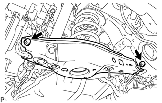
Loosen the 2 bolts of the rear No. 2 suspension arm.
Note
-
Do not remove the bolts and nuts. Loosen them.
-
Since a stopper nut is used, loosen the bolt.
-
-
-
DISCONNECT REAR SHOCK ABSORBER ASSEMBLY LH
-
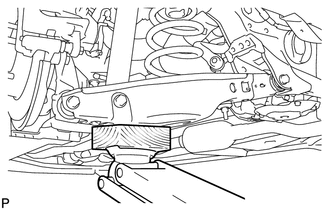
Support the rear No. 2 suspension arm with a jack using a wooden block.
-
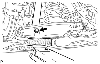
Remove the bolt while holding the nut and disconnect the rear shock absorber.
-
-
REMOVE REAR COIL SPRING LH
-
REMOVE REAR UPPER COIL SPRING INSULATOR LH
-
REMOVE REAR LOWER COIL SPRING INSULATOR LH
-
REMOVE REAR NO. 2 SUSPENSION ARM ASSEMBLY LH
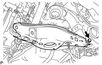
-
Remove the bolt, nut and rear No. 2 suspension arm from the suspension member.
Note
Since a stopper nut is used, loosen the bolt.
-